REMOVAL AND INSTALLATION


Pre-removal operation
  • Fuel Line Pressure Reduction [Refer to GROUP 13C - On-vehicle Service, Fuel Pump Connector Disconnection (How to Reduce Pressurized Fuel Lines) ].
  • Engine Coolant Draining (Refer to GROUP 14 - On-vehicle Service, Engine Coolant Replacement <4B1, 6B3> ).
  • Alternator Removal (Refer to GROUP 16 - Charging System, Alternator Assembly <6B3> ).
  • Thermostat Housing Removal (Refer to GROUP 14 - Water Hose and Water Pipe <6B3 (Vehicles without EGR)> ).
  • Thermostat Housing Removal (Refer to GROUP 14 - Water Hose and Water Pipe <6B3 (Vehicles with EGR)> ).
  • Intake Manifold Removal (Refer to GROUP 15 - Intake Manifold <6B3> ).
  • Exhaust Manifold Removal (Refer to GROUP 15 - Exhaust Manifold <6B3> ).
  • Timing Belt Removal (Refer to ).

Post-installation operation
  • Timing Belt Installation (Refer to ).
  • Exhaust Manifold Installation (Refer to GROUP 15 - Exhaust Manifold <6B3> ).
  • Intake Manifold Installation (Refer to GROUP 15 - Intake Manifold <6B3> ).
  • Thermostat Housing Installation (Refer to GROUP 14 - Water Hose and Water Pipe <6B3 (Vehicles without EGR)> ).
  • Thermostat Housing Installation (Refer to GROUP 14 - Water Hose and Water Pipe <6B3 (Vehicles with EGR)> ).
  • Alternator Installation (Refer to GROUP 16 - Charging System, Alternator Assembly <6B3> ).
  • Engine Coolant Refilling (Refer to GROUP 14 - On-vehicle Service, Engine Coolant Replacement <4B1, 6B3> ).
  • Fuel Leak Check.


Removal steps


1.
Blow-by hose connection


2.
PCV hose connection


3.
Engine oil level gauge


4.
Ignition coil connector


5.
Ignition coil


6.
Rocker cover


7.
Rocker cover gasket


8.
Oil pipe


9.
Gasket


10.
Camshaft position sensor connector
<<A>>
>>B<<
11.
Camshaft sprocket


12.
Idler pulley


13.
Timing belt rear cover
<<B>>
>>A<<
14.
Left bank cylinder head assembly

>>A<<
15.
Cylinder head gasket


16.
Blow-by hose connection


17.
Breather hose connection


18.
Ignition coil connector


19.
Ignition coil


20.
Rocker cover


21.
Rocker cover gasket


22.
Engine oil control valve connector


23.
Engine oil pressure switch connector


24.
Solenoid valve connector
<<B>>
>>A<<
25.
Right bank cylinder head assembly

>>A<<
26.
Cylinder head gasket

REMOVAL SERVICE POINTS


<<A>> CAMSHAFT SPROCKET REMOVAL


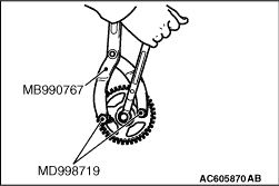
Use the following special tools to remove the camshaft sprocket.

  • Front hub and flange yoke holder (MB990767)
  • Pin (MD998719)

<<B>> CYLINDER HEAD ASSEMBLY REMOVAL


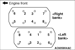
Loosen the cylinder head bolts in two or three steps in the order of the numbers shown in the illustration, and remove the cylinder head assembly.

INSTALLATION SERVICE POINTS


>>A<< CYLINDER HEAD GASKET/CYLINDER HEAD ASSEMBLY INSTALLATION


1.
caution Be careful that no foreign material gets into the cylinder, coolant passages or oil passages. Engine damage may result.
Use a scraper to clean the gasket surface of the cylinder head assembly and cylinder block.
2.Install the cylinder head gasket and cylinder head assembly to the cylinder block.

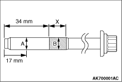
3.Check in the following procedure before reusing the cylinder head bolt.
(1) Measure the outside diameter "A".
(2) Measure the smallest outside diameter "B" within the range "X" shown in the illustration.
(3) If the difference of outside diameter of thread exceeds the limit, replace the cylinder head bolt.
Limit: 0.1mm


4.Tighten the cylinder head bolts to the specified torque in the order shown in the illustration (in two or three cycles).
Tightening torque: 45 ± 2 N·m

5.
caution
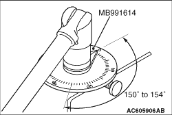
  • If the cylinder head bolt is turned less than 150 to 154 degrees, proper fastening performance may not be achieved. Be sure to turn the cylinder head bolt exactly 150 to 154 degrees.
  • If the cylinder head bolt is overtightened, loosen the cylinder head bolt completely and then retighten it by repeating the tightening procedure from step 3.
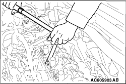
Using special tool angle gauge (MB991614), tighten the cylinder head bolt another 150 to 154 degrees again.

>>B<< CAMSHAFT SPROCKET INSTALLATION


1.Use the following special tools in the same way as during removal to install the camshaft sprocket.

  • Front hub and flange yoke holder (MB990767)
  • Pin (MD998719)
2.Tighten the camshaft sprocket mounting bolt to the specified torque.
Tightening torque: 90 ± 10 N·m