|
1.
| caution |
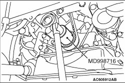
Never turn the crankshaft anti-clockwise.
|
Use special tool crankshaft wrench (MD998716) to turn the crankshaft clockwise to align each timing mark and to set the No. 1 cylinder to compression top dead centre.
|
|
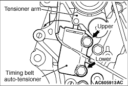
2.Remove the upper mounting bolt of the timing belt auto-tensioner.
3.
| caution |
The timing belt auto-tensioner rotates centring on the flange bolt due to the rod thrust, so please make sure your finger is not trapped.
|
Loosen the lower mounting bolt of the timing belt auto-tensioner slowly and slide the timing belt auto-tensioner slightly. Remove the rod from the tensioner arm.
4.Remove the lower mounting bolt of the timing belt auto-tensioner.
|
|
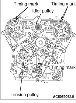
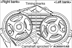
1.Check that the timing marks of each sprocket are aligned.
2.If the timing belt is to be reused, chalk an arrow on the flat side of the belt, indicating the clockwise direction.
3.Loosen the centre bolt of the tensioner pulley, then remove the timing belt.
|
|
1.
| caution |
Always bleed the timing belt auto-tensioner of air before installing the timing belt auto-tensioner (Refer to  ). ).
|
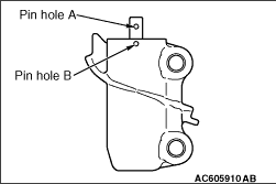
Insert the pin into the rod of the timing belt auto-tensioner under the following procedures.
(1)
|
|
| caution |
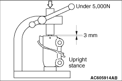
Notable factors for inserting pin
- Always use the vertical press and put the timing belt auto-tensioner vertically.
- Do not apply the load of 5,000 N or more to the rod.
- Do not press the rod beyond the dimension shown in the illustration.
|
|
Put the timing belt auto-tensioner vertically to the vertical press not to be in the sideways direction.
(2)
Slowly close the vice to force the rod in until the hole (A) of the rod is lined up with set hole (B) of the cylinder.
(3)
Insert a pin into the set holes.
(4)
Remove the timing belt auto-tensioner from the vice.
2.Install the timing belt auto-tensioner with the setting pin, and tighten the mounting bolts to the specified torque.
Tightening torque: 23 ± 6 N·m
|
|
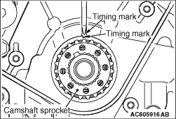
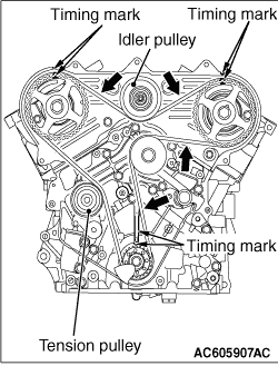
3.Align the timing marks on the camshaft sprockets with those on the timing belt rear cover and the timing mark on the crankshaft sprocket with that on the engine block as shown in the illustration.
|
|
4.
| caution |
The camshaft sprocket (right bank) can turn easily due to the spring force applied, so be careful not to get your fingers caught.
|
Install the timing belt by the following procedure so that there is no deflection in the timing belt between each sprocket and pulley.
(1)
Crankshaft sprocket
(2)
Water pump pulley
(3)
Camshaft sprocket (Left bank)
(4)
Idler pulley
(5)
Camshaft sprocket (Right bank)
(6)
Tensioner pulley
5.Turn the camshaft sprocket (Right bank) anti-clockwise until the tension side of the timing belt is firmly stretched. Check all the timing marks again.
|
|
6.Use special tool crankshaft wrench (MD998716) to turn the crankshaft 1/4 turn anti-clockwise, then turn it again clockwise until the timing marks are aligned.
7.Remove the setting pin that has been inserted into the timing belt auto-tensioner.
8.Turn the crankshaft clockwise twice to align the timing marks.
|
|
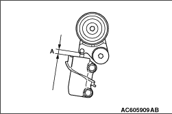
9.Wait for at least five minutes, then check that the timing belt auto-tensioner pushrod extends within the standard value range.
Standard value (A): 9.1 - 13.4 mm
10.If not, repeat the operation in steps 1 to 8 above.
11.Check again that the timing marks of the each sprockets are aligned.
|
)
)
)
)
)
)
)
)
)
)