|
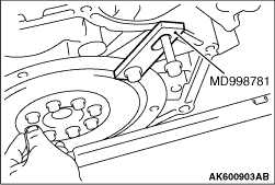
1.Using special tool Flywheel stopper (MD998781), hold the drive plate.
2.Remove the drive plate bolt.
|
|
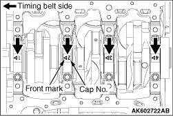
Using indelible ink, show the front mark and the cap No. on the bearing cap if they cannot
be seen.
|
|
|
1.Apply the engine oil to the thread portions and the sealed portions on the installation
bolts.
|
|
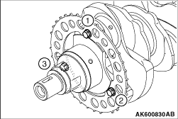
2.In accordance with the tightening order shown in the illustration, tighten the crankshaft
sensing ring to the specified torque.
Tightening torque: 12 ± 2 N·m
|
|
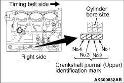
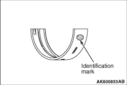
1.If the upper crankshaft bearing is replaced, select based on the identification mark of
cylinder block (illustrated) and the table shown below.
|
|
Crankshaft journal (Upper)
|
Crankshaft bearing
|
Identification mark
|
Identification mark
|
Number 1 and 4 journal
|
1
|
1
|
2
|
2
|
3
|
3
|
Number 2 and 3 journal
|
0
|
0
|
1
|
1
|
2
|
2
|
|
|
|
2.The upper crankshaft bearing has the identification mark on the location shown in the
illustration.
3.Install the upper selected crankshaft bearing.
|
|
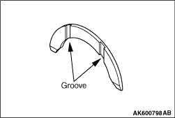
1.Install the thrust bearing in the No.3 bearing bore in the cylinder block and in the bearing
cap. For easier installation, apply engine oil to the bearings; this will help hold them in position.
2.The thrust bearings must be installed with their groove toward the crankshaft web.
|
|
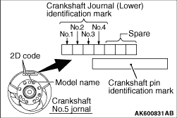
1.If the lower crankshaft bearing is replaced, select based on the identification mark of
crankshaft (illustrated) and the table shown below.
|
|
Crankshaft journal (Lower)
|
Crankshaft bearing
|
Identification mark
|
Identification mark
|
0
|
0
|
1
|
1
|
2
|
2
|
3
|
3
|
4
|
4
|
|
|
|
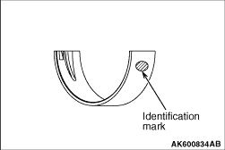
2.The lower crankshaft bearing has the identification mark on the location shown in the
illustration.
3.Install the lower selected crankshaft bearing.
|
|
|
1.Before installing the bearing cap bolt, check the bolt screw head is not damaged.
If the screw head extremely gets damaged, replace it with a new bolt. The standard length of the
new bolt measured from under the head is as follows:
Standard value: 91.2 - 92.2 mm
|
|
|
2.Attach the bearing cap on the cylinder block as shown in the illustration.
|
|
|
3.Tighten the bearing cap bolts to specified torque in the sequence shown in the illustration.
Tightening torque: 24 ± 2 N·m
|
|
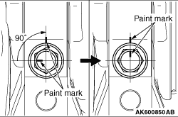
4.Make a paint mark on the head of each bolt.
5.
| caution |
- If the bolt is overtightened,
loosen the bolt completely and then retighten it by repeating the tightening procedure from
step 2.
- If the bolt is turned less than 90°, proper fastening performance may not
be achieved. Be sure to turn the bolt exactly 90°.
|
Make a paint mark on the bearing cap 90° from the paint mark made on the bolt,
in the direction of tightening the bolt.
6.Turn each bolt 90° in the tightening sequence specified in step 2, and make
sure that the paint marks on the bolt and cap are aligned.
7.Check that the crankshaft rotates smoothly.
|
|
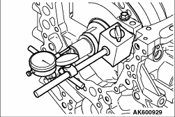
8.Check the end play. If it exceeds the limit value, replace the thrust bearing.
Standard value: 0.05 - 0.25 mm
Limit: 0.3 mm
|
|
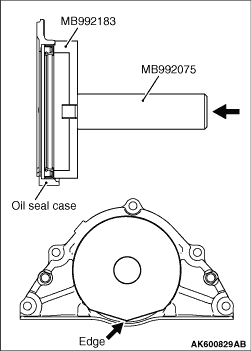
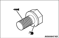
Using special tools Handle (MB992075) and Crankshaft rear oil seal installer (MB992183),
press-fit a new crankshaft rear oil seal into the oil seal case.
| note |
Put the edge position in place as shown in the illustration.
|
|
|
|
1.Completely remove liquid gasket adhering to the oil seal case and cylinder block.
|
|
|
2.Using white gasoline and so on, degrease the oil seal case and cylinder block.
|
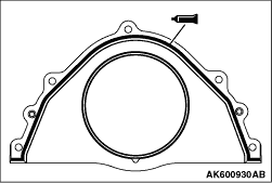
|
3.Apply a 2.5 ± 0.5 mm diameter bead of sealant to the oil seal case.
Specified sealant:
Three bond 1227D, Three bond 1217G (MITSUBISHI GENUINE PART 1000A923), Three bond
1207F (MITSUBISHI GENUINE PART MD970389), LOCTITE 5971, LOCTITE 5970, LOCTITE 5900 or equivalent
4.Apply a small amount of engine oil to the entire circumference of the oil seal lip
section, and place the oil seal case on the cylinder block.
| note |
Install the oil seal case within 15 minutes after applying liquid gasket.
|
| note |
Then wait at least one hour. Never start the engine or let engine oil or coolant touch
the adhesion surface during that time.
|
|
|
|
1.Cleanly remove sealant, oil and dust on the drive plate bolt, the drive plate and
the threaded portions of the crankshaft.
|
|
2.Apply oil to the drive plate and the seating surface of the drive plate bolt.
3.Apply oil to the threaded hole of the crankshaft
4.Apply sealant to the thread portions of the drive plate bolt.
Specified sealant:
Three bond 1324 or equivalent
|
|
5.Using special tool Flywheel stopper (MD998781), hold the drive plate.
6.Tighten the drive plate bolt to the specified torque.
Tightening torque: 76 ± 4 N·m
|
)

)
)
)
)
)
)
)
)
)
)
)
)
)
)