|
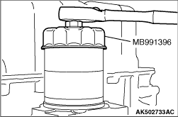
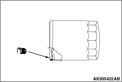
Use special tool oil filter wrench (MB991396) to remove the oil filter.
|
|
|
1.Remove oil pan tightening bolts.
|
|
2.
| caution |
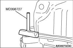
Lightly tap the oil pan FIPG cutter to drive in, taking care not to damage
the ladder frame and oil pan sealed area.
|
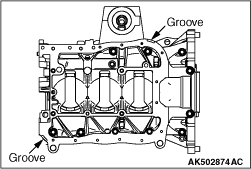
Lightly tap special tool oil pan FIPG cutter (MD998727) to drive in the illustrated groove
of the oil pan and ladder frame.
|
|
3.Lightly tap and slide special tool oil pan FIPG cutter (MD998727) to remove the oil pan.
|
|
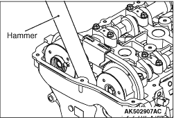
If the timing chain case is difficult to remove, insert a hammer handle as shown in the
illustration and lightly pry it.
|
|
|
1.
| caution |
Be sure to remove liquid gasket that has entered mounting holes and O-ring
grooves.
|
Completely remove liquid gasket adhering to the timing chain case, cylinder block and
cylinder head.
|
|
|
2.
| caution |
Sufficiently check that there is no residual oil on the
place where degreasing is performed. If fingerprints are left, do not touch it with bare hands
after the degreasing, since the oils from your fingers will harm the seal ability.
|
Using white gasoline and so on, degrease the surface where the liquid gasket is applied
and the contact surface between the cylinder block and the cylinder head.
|
|
3.
| caution |
Install the timing chain case within three minutes after applying
liquid gasket.
|
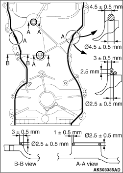
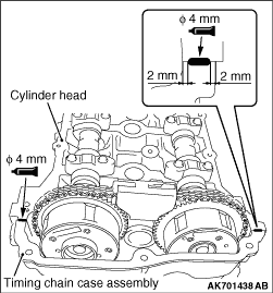
Apply liquid gasket of 2.5 ± 0.5 mm in thickness to the timing chain case. For
illustrated A locations, however, apply liquid gasket of 4.5 ± 0.5 mm in diameter or liquid
gasket of 2.5 ± 0.5 mm by putting one on top of another as shown in the illustration.
Specified sealant:
Three bond 1217G (MITSUBISHI GENUINE PART 1000A923) or equivalent
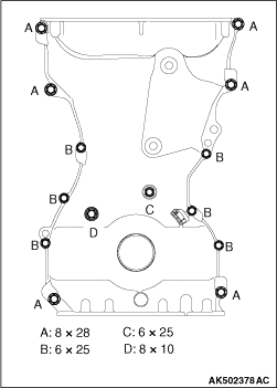
4.Install the timing chain case.
| note |
Be careful to install mounting bolts because they are different in length.
|
|
|
5.Tighten timing chain case mounting bolts to the specified torque.
Tightening torque
A: 24 ± 4 N·m
B: 10 ± 2 N·m
C: 10 ± 2 N·m
D: 13 ± 1 N·m
|
|
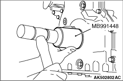
1.Apply engine oil to the internal circumference of the oil seal.
2.Use special tool crankshaft front oil seal installer (MB991448) to install the front
oil seal on the timing chain case.
|
|
|
1.Completely remove liquid gasket adhering to the cylinder block and oil pan.
|
|
|
2.Using white gasoline and so on, degrease the cylinder block and oil pan.
|
|
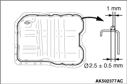
3.Apply liquid gasket of Φ2.5 ± 0.5 mm of thickness in diameter to
the illustrated area of the oil pan.
Specified sealant:
Three bond 1227D, Three bond 1217G (MITSUBISHI GENUINE PART 1000A923), Three bond
1207F (MITSUBISHI GENUINE PART MD970389), Loctite 5971, Loctite 5970, Loctite 5900 or equivalent
4.Tighten the oil pan to the specified torque of 10 ± 2 N·m (M6) and
29 ± 2 N·m (M8).
|
|
|
1.Completely remove liquid gasket adhering to the cylinder head cover, timing chain
case and cylinder head.
|
|
|
2.Using white gasoline and so on, degrease the cylinder head cover, timing chain case
and cylinder head.
|
|
| caution |
Install the cylinder head cover immediately after liquid gasket
is applied.
|
3.Appropriately use a minimum amount of sealant. Besides, be careful not to allow sealant
to squeeze out from the application area.
Apply liquid gasket of 4 mm of thickness in diameter.
Specified sealant:
Three bond 1227D, Three bond 1217G (MITSUBISHI GENUINE PART 1000A923) or equivalent
|
|
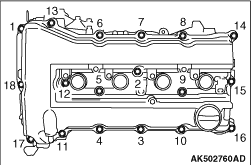
4.Tighten the cylinder head cover to the tightening torque of 3.0 ± 1.0 N·m
in the order shown in the illustration.
5.Then, tighten it to the specified torque of 5.5 ± 0.5 N·m in the
same order.
|
|
|
1.Apply a small amount of new engine oil to the engine oil cooler gasket, and install
it to the engine oil cooler assembly.
|
|
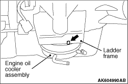
2.Align the projection for positioning the engine oil cooler assembly with the position
of ladder frame as shown in the figure, and install the engine oil cooler assembly.
3.Tighten the engine oil cooler bolt to the specified torque.
|
|
|
1.Clean the oil filter mounting surface of the ladder frame.
|
|
2.Apply engine oil to the O-ring of the oil filter.
|
|
| caution |
Use special tool filter wrench (MB991396) to install the
oil filter. Tightening it by hand causes oil leakage due to lack of torque.
|
3.Screw in the oil filter. When the O-ring contacts the mounting surface, use a filter
wrench to tighten it 3/4 turns (14 ± 2 N·m).
|
)

)
)
)
)
)
)
)
)
)
)
)
)