|
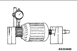
1.Support the armature with a pair of V block and turn it to measure the runout of the surface
not rubbed by the brushes using a dial gauge.
Standard value: 0.05 mm or less
Limit: 0.1 mm
|
|
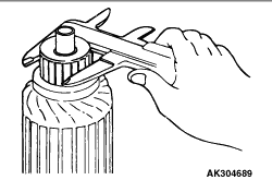
2.Measure the diameter of the commutator.
Standard value: 29.4 mm
Limit: 28.8 mm
|
|
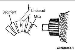
3.Measure the depth of the undercut between segments.
Standard value: 0.5 mm
Limit: 0.2 mm
|
|
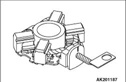
Push the brush into the brush holder to make sure that the spring is working on the brush.
If the spring is not working, replace the brush holder.
|
|
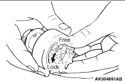
1.Make sure that the pinion cannot be turned counterclockwise and can be turned clockwise
freely.
2.Check the pinion for abnormal ware and damage.
|
|
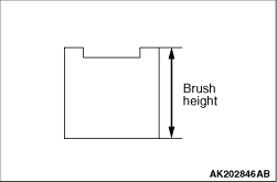
1.Check the commutator contacting surface of each brush for abnormal roughness. Also check
the height of the brush. Replace the brush holder if the height is lower than the limit.
Limit: 7.0 mm
2.When the contact surface of the brush is rectified or the brush holder is replaced,
recondition the contact surface with sandpaper wrapped around the commutator.
|
|
|
1.Check the armature coil for short circuit as follows.
|
|
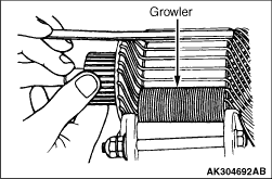
2.Set the armature in a growler.
| caution |
Clean the surface of the armature thoroughly before performing the test.
|
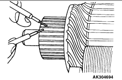
3.While holding a thin strip of iron against the armature in parallel with its axis,
turn the armature slowly. The armature is normal if the iron strip is not attracted to the armature
or it does not vibrate.
|
|
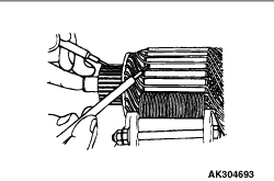
4.Check the insulation between commutator segments and armature coils. The armature coils
are properly insulated if no continuity is present.
|
|
5.Check continuity between a segment and another. There is no open circuit in the tested
coil if there is continuity.
|
)
)
)
)
)
)
)
)
)