TRANSMISSION CONTROL REMOVAL AND INSTALLATION


warning When removing and installing the transmission control cable and shift lock cable unit, be careful not to hit the SRS-ECU.
Pre-removal operation
  • Front floor console assembly removal (Refer to GROUP 52A - Floor Console Assembly .)

Post-installation operation
  • Front floor console assembly installation (Refer to GROUP 52A - Floor Console Assembly .)
  • Key interlock mechanism check (Refer to .)
  • Shift lock mechanism check (Refer to .)
  • Selector lever operation check (Refer to .)


Selector lever assembly and transmission control cable assembly removal steps


·
Move the selector lever to the "N" position.
<<A>>

1.
Selector lever knob
<<B>>

2.
Shift indicator panel

>>B<<
3.
Key interlock cable connection (selector lever side)


4.
Transmission control cable connection (selector lever side)


·
Connectors and harnesses connections


5.
Selector lever assembly


·
Battery and battery tray


·
Air Cleaner (Refer to GROUP 15 - Air Cleaner .)

>>A<<
6.
Transmission control cable connection (transmission side)


·
Heater unit assembly (Refer to GROUP 55 - heater unit and blower assembly removal and installation .)


7.
Transmission control cable

REMOVAL SERVICE POINTS


<<A>> SELECTOR LEVER KNOB REMOVAL


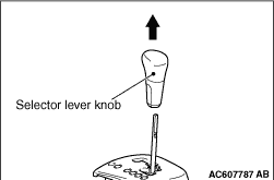
Pull out the selector lever knob to the direction of arrow shown in the figure.

<<B>> SHIFT INDICATOR PANEL REMOVAL


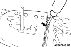
Insert the slotted head screwdriver into the arrow-indicated point as shown in the figure to pry the claw, and then remove the shift indicator panel.

INSTALLATION SERVICE POINTS


>>A<< TRANSMISSION CONTROL CABLE (TRANSMISSION SIDE) INSTALLATION


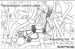
1.Move the selector lever and manual control lever to the "N" position.
2.Use the adjusting nut to tighten the transmission control cable to the specified torque.
Tightening torque: 9.5 ± 3.5 N·m

>>B<< KEY INTERLOCK CABLE INSTALLATION


caution Leave the ignition switch in the "LOCK" (OFF) position until the key interlock cable installation is completed.
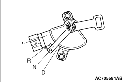
1.Move the selector lever to the "P" position and turn the ignition switch to the "LOCK" (OFF) position.

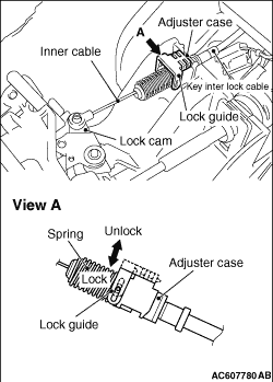
2.Install the tip of the key interlock cable to the lock cam of the selector lever assembly, taking care not to twist the inner cable.
3.Install the adjuster case with its lock guide pulled up (unlocked).
4.Securely push down the lock guide to lock it.
note The lock position of the key interlock cable is automatically adjusted by a spring.