|
|
Replace the belt if any of the following conditions exist:
|
|
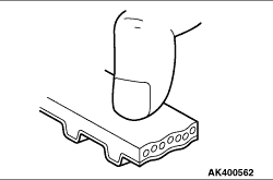
1.Hardening of rubber backing.
Back side should be glossy without resilience and leave no indent when pressed with fingernail.
|
|
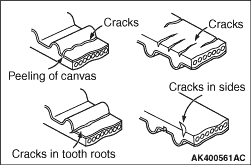
2.Cracks on rubber back.
3.Cracks or peeling of canvas.
4.Cracks at bottom of ribs.
5.Cracks on belt sides.
|
|
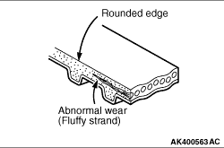
6.Abnormal wear of belt sides. Normal wear is indicated if the sides are sharp as if cut
by a knife. Abnormal wear is indicated if the sides are ragged.
|
|
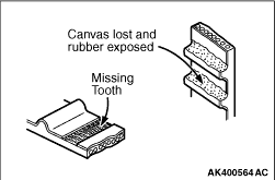
7.Abnormal wear on teeth.
Initial stage:
Canvas worn (fluffy canvas fibers, rubbery texture gone, white discolouration, canvas
texture indistinct)
Final stage:
Canvas worn, exposing rubber (tooth width reduced)
8.Missing tooth.
|
|
|
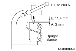
If the rod moves slightly when pushing down the rod with 100 - 200 N, bleed the
auto-tensioner of air because air enters.
|
|
1.Set the auto tensioner as shown in the illustration.
2.Press the rod slowly down to the lowest point "A" shown in the illustration.
3.Repeat the procedure 2 three times.
4.While the rod is projected at the point "B" shown in the illustration, push the rod
with 100 - 200 N. Check the enough stiffness. If the stiffness is not enough, replace
the auto tensioner.
5.Press the rod slowly down. Put the pin through the hole and fix it.
| caution |
After the air bleeding operation has been completed, do not
tilt the auto-tensioner to 60° or more from the right angle position.
|
|
|
|
1.Remove the rocker cover and ignition coil.
|
|
2.
| caution |
Rotate the crankshaft clockwise at any time.
|
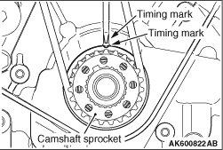
Turn the crankshaft clockwise, and align the crankshaft sprocket timing mark with the
position shown in the illustration.
|
|
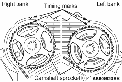
3.At that time, check the right and left camshaft sprocket timing marks are in position
as shown in the illustration.
|
|
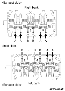
4.Measure the valve clearances marked with arrows shown in the illustration.
A: When No.1 cylinder is on the top dead centre of compression stroke.
B: When No.4 cylinder is on the top dead centre of compression stroke.
| note |
The valve clearance adjustment at the exhaust side is not necessary because the auto lash
adjuster exists.
|
|
|
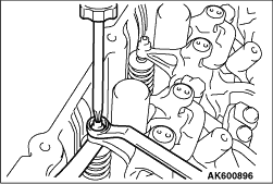
5.Using a free gauge, adjust the clearance between the valve stem end and the adjusting
screw.
Standard value: 0.07 - 0.13 mm
6.Hold the adjusting screw not rotating through a driver and then tighten the rock nut.
|
|
7.Rotate the crankshaft one time clockwise and then align the timing mark with the timing
mark on the crankshaft sprocket. (Place No. 4 cylinder on the top dead centre of compression
stroke.)
8.Adjust the valve clearance for the rest of the valves.
9.Install the rocker cover and ignition coil.
|
)
)
)
)
)
)
)
)
)