|
| caution |
Be careful not to allow retainer holder C to interfere with the wall of the
tappet hole and to damage it.
|
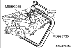
Use a special tool to compress the valve spring and to remove the retainer lock.
- Valve spring compressor (MD998735)
- Retainer holder C (MB992089)
| note |
Store removed parts such as valves and springs with tags describing cylinder No. and installed
position attached for reassembly.
|
|
|
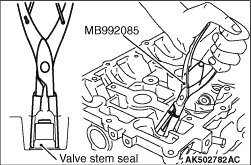
Use special tool Valve stem seal pliers (MB992085) to firmly pinch the base (larger external
shape) of the stem seal and twist it right and left for pulling out.
|
|
1.Apply a thin coat of engine oil to a new valve stem seal.
|
|
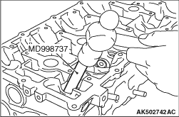
2.Use special tool Valve stem seal installer (MD998737) to press fit the valve stem seal
into the valve guide with the valve stem used as a guide.
|
|
Use a special tool to compress the valve spring and to install the retainer lock.
- Valve spring compressor (MD998735)
- Retainer holder C (MB992089)
|
|
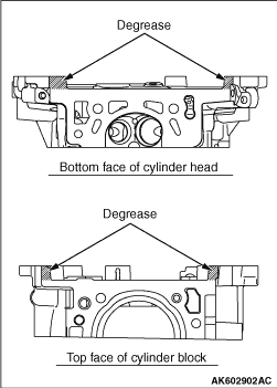
1.Completely remove the liquid gasket on the upper plane of the cylinder block and the lower
plane of the cylinder head.
2.
| caution |
Sufficiently check that there is no residual oil on the
place where degreasing is performed. If fingerprints are left, do not touch it with bare hands
after the degreasing, since the oils from your fingers will harm the seal ability.
|
Degrease the place specified in the illustration.
|
|
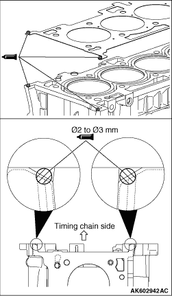
3.As shown in the illustration, apply a 2.5 ± 0.5 mm of sealant to the top face
of cylinder block.
Specified sealant:
Three bond 1217G or exact equivalent
4.Install the cylinder head gasket.
| note |
Check that the centre of the liquid gasket is located toward the cylinder gasket in the position
specified in the illustration.
|
5.As shown in the illustration, apply a 2.5 ± 0.5 mm of sealant to the top
face of cylinder head gasket.
Specified sealant:
Three bond 1217G or exact equivalent
6.Install the cylinder head assembly.
|
|
|
1.Install new cylinder head bolts and washers in the following procedure.
| note |
Cylinder head bolts and washers must not be reused.
|
|
|
|
2.Apply an appropriate amount of engine oil to top and bottom surfaces of washers and
threaded portion of bolts.
|
|
|
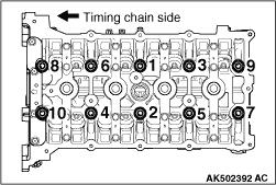
3.Install cylinder head bolts to the cylinder head.
| note |
Bolts and washers are different parts for bolts on the timing chain side.
|
|
|
4.Tighten cylinder head bolts in several steps to the specified torque of 35 ± 2
N·m according to the assembly order.
|
|
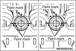
5.Put a paint mark on all of cylinder head bolt heads and cylinder head.
6.
| caution |
- When the tightening
angle is smaller than the specified tightening angle, the appropriate tightening capacity cannot
be secured.
- When the tightening angle is larger than the specified tightening angle, remove
the bolt to start from the beginning again according to the procedure.
|
Tighten the cylinder head 90° according to the tightening order.
Tighten it further 90° and make sure that the paint mark on the cylinder head
bolt is in a straight line with that on the cylinder head.
|
)

)
)
)
)
)
)
)
)