|
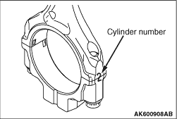
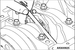
1.Mark the cylinder number on the side of the connecting rod big end for correct reassembly.
2.Keep the removed connecting rods, caps, and bearings in order according to the cylinder number.
|
|
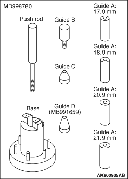
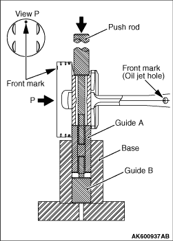
1.The special tool Piston pin setting tool (MD998780) consists of the elements shown in
the illustration.
2.When removing the piston pin, the special tool Guide D (MB991659) is also used.
|
|
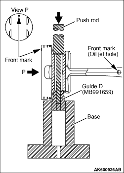
3.Insert Push rod, into the piston from the front mark side, then attach Guide D, to the
push rod.
4.Place the piston and connecting rod assembly on Base, with the front mark facing up.
5.Use a press to remove the piston pin.
| note |
Keep the disassembled pistons, piston pins and connecting rods per cylinder.
|
|
|
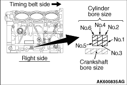
1.When replacing the piston, note the cylinder bore size mark on the cylinder block as illustrated,
and select a piston according to the flowing table.
|
|
Cylinder bore size mark
|
Piston size mark
|
A
|
A
|
B
|
B
|
|
| note |
The piston size mark shows on the top of the piston.
|
2.Insert the push rod into the piston pin and install the guide A.
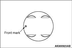
3.Align the front mark of the piston with that of the connecting rod. Align the piston
with the connecting rod.
4.Apply engine oil to the outer circumference of the piston pin.
5.Insert the piston pin guide A installed at step 2 into the pin hole from the front
mark of the piston.
|
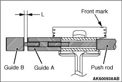
|
6.Screw the guide B into A until the clearance "L" reaches 3.75 mm between A and B.
|
|
7.Place the piston and connecting rod assembly onto Base, with the front marks facing up.
8.Install the piston pin using a press. If the required press force is less than the
standard value, replace the piston and piston pin assembly or the connecting rod, or both.
Standard value: 5,000 - 15,000 N
|
|
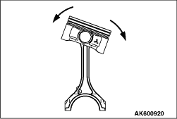
9.Check that the piston moves smoothly.
|
|
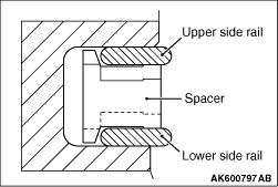
1.Fit the oil ring spacer into the piston ring groove.
| note |
The side rails and spacer may be installed in either direction.
|
| caution |
Do not use any piston ring expander when installing the side
rail. If will break the side rail.
|
|
|
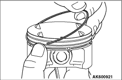
2.Install the upper side rail.
To install the side rail, first fit one end of the rail into the piston groove, then press
the remaining portion into the position by finger. See illustration.
3.Install the lower side rail in the same procedure as described in step 2.
4.Make sure that the side rails move smoothly in both directions.
|
|
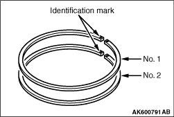
To prevent wrong installation, check the identification mark of each piston ring. The
identification mark is stamped near the ring gap:
Identification mark
Number 1 ring: 1T
Number 2 ring: 2T
|
|
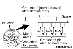
1.If the connecting rod bearing is replaced, select based on the identification mark of
crankshaft (illustrated) and the table shown below.
|
|
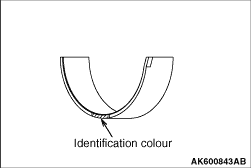
2.Every connecting rod bearing is identified by the paint mark at the illustrated location.
|
|
Crankshaft pin identification mark
|
Bearing identification colour
|
1
|
Black
|
2
|
Purple
|
3
|
Green
|
|
3.Install the selected bearing in the big end and in the cap of the connecting rod.
|
|
1.Liberally coat the circumference of the piston, piston ring, and oil ring with engine
oil.
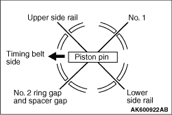
2.Arrange the piston ring and oil ring gaps (side rail and spacer) as shown in the illustration.
3.Rotate the crankshaft so that the crank pin is on the centre of the cylinder bore.
|
|
4.Insert the piston and connecting rod assembly into the cylinder with the front mark on
the piston crown pointing to the timing belt side.
|
|
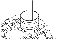
5.Using a suitable piston ring compressor tool, install the piston and connecting rod assembly
into the cylinder block.
|
|
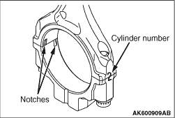
1.Verifying the mark made during disassembly, install the bearing cap to the connecting
rod. If the connecting rod is new with no index mark, make sure that the bearing locking notches
are on the same side as shown.
|
|
2.Make sure that the connecting rod big end side clearance meets the specification.
Standard value: 0.10 - 0.25 mm
Limit: 0.4 mm
|
|
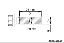
1.Check in the following procedure before reusing the connecting rod bolt.
(1)
Measure the outside diameter "A."
(2)
Measure the smallest outside diameter "B" within the range "X" shown in the illustration.
(3)
If the difference of outside diameter of thread exceeds the limit, replace the connecting
rod bolt.
Limit: 0.1 mm
2.Apply engine oil to the threaded portion and seating face of the bolt.
3.To correctly install the cap, loosely install the bolts with fingers.
4.Alternately, tighten the bolts in several steps to the specified torque of 20 ± 2 N·m.
|
|
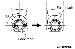
5.Make a paint mark on the head of each bolt.
6.
| caution |
- When the tightening
angle is smaller than the specified tightening angle, the appropriate tightening capacity cannot
be secured.
- When the tightening angle is larger than the specified tightening angle, remove
the bolt to start from the beginning again according to the procedure.
|
Put another paint mark on the bolt head at 90° in the tightening direction from
the first paint mark.
7.Tighten the bolt 90°. The paint mark on the connecting rod should be aligned
with the paint mark on the bolt.
|
)

)
)
)
)
)
)
)
)
)
)
)
)
)
)
)
)
)
)
)