|
|
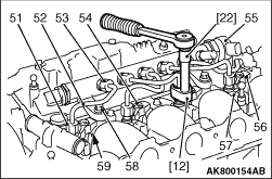
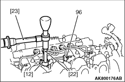
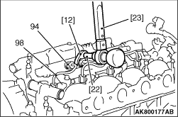
[12] Pipe spanner (-).4220-T.C
|
|
|
[22] Extension (-).1603-E
|
|
|
[23] Torque wrench 4220-T.B/ 4220-T.A
|
|
|
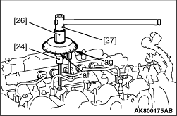
[24] Socket for allen screws (-).1608-D
|
|
|
[25] Torque wrench (-).1608-A
|
|
|
[26] Adaptor for tightening diesel injector (-).1608-C
|
|
|
[27] T-extension (-).1603-E (K1608 kit)
|
|
|
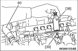
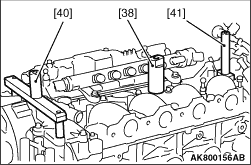
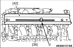
[38] Diesel injector end-piece 1616.ZZ-F2
|
|
|
[40] Diesel injector extractor support 1616.ZZ-F1
|
|
|
[41] Diesel injector extractor support 1616.ZZ-F3
|
|
|
[42] Diesel injector extractor rail 1616.ZZ-B
|
|
Unscrew:
1.The 5 unions (53); Using tools [12] and [22].
2.The 4 unions (51); Using tools [12] and [22].
3.Remove: The 4 high-pressure fuel supply pipes (52):
4.The bolts (54).
5.The clamps (56).
| caution |
Recover the support pins (59)
|
6.Remove the injectors (57).
7.Remove the bolts (58).
8.Remove the fuel high-pressure common injection rail (55).
| note |
If it is difficult to remove the injectors, use the following procedure.
|
|
|
9.Remove the tube (60).
10.Fits the blanking piece [39] onto the diesel injector.
11.Screw the tool [38] onto the diesel injector.
|
|
12.Install the tool [40] (On the timing side, in contact with the cylinder
head cover).
13.Install the tool [41] (On the gearbox side, in contact with the
camshaft main bearing cap casting).
|
|
14.Fix the tool [42] on the tools [40] and [41].
15.Fit the bolt "d" of tool [38] through the slot in tool [42].
16.Tighten the bolt "d" of tool [38] until the diesel injector is extracted.
| note |
If it is impossible to remove the diesel injector. Attempt the extraction using the extractor:
CTIA 0413 or PICHLER 60383305 (Replacement Parts reference; See workshop equipment). It is imperative
that the manufacturers’ manuals are used.
|
|
|
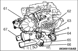
17.Exert a counter-torque at "e".
18.Loosen the union (64).
19.Remove vacuum pump (61).
20.Remove the high-pressure fuel pump (62) with the fuel entry pipe.
21.Remove the high-pressure fuel pipe (63).
22.Remove the bolt (66).
23.Remove the bracket (65).
24.Remove the coolant outlet housing (67)
|
|
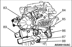
1.Install a new seal on the coolant outlet housing (89).
Install
2.Tighten the coolant outlet housing (89) to torque of 8 ± 1 N·m.
3.Install the clamp (87).
4.Tighten the bolt (88) to torque of 8 ± 1 N·m.
5.Install the high-pressure fuel pipe (85) (new)
6.Install the high-pressure fuel pump (84) with the entry pipe.
7.Install the vacuum pump (83).
8.Tighten the fixings of the high-pressure fuel pump (84) to torque 22 ± 2
N·m.
|
|
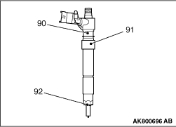
9.Preparing a diesel injector:
10.Install the centring ring (91) on the diesel injector (90).
11.Install the new copper seal (92) on the diesel injector (90).
|
|
| caution |
Refit the diesel injectors observing the marks made on removal (if the injectors are to
be reused)
|
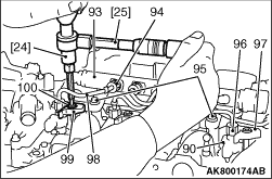
1.Reposer:
2.The diesel injectors (90).
3.The clamp (99) thrust pins (97).
4.The clamps (99).
5.The fuel high-pressure common injection rail (93).
6.The screws (95), without tightening them.
7.The high-pressure fuel pipes (98).
| caution |
The refitting of the 4 high-pressure fuel pipes (98) and
the tightening of the unions (96), (94) by hand to the end of the thread positions the diesel injectors.
|
8.Tighten by hand to the end of the thread:
9.The 4 high-pressure fuel pipe (98) unions (96) on the diesel injectors (90).
10.The 5 unions (94) of the high-pressure fuel pipes (98) and (85) on the high-pressure
fuel injection common rail (93).
11.Pre-tighten the bolts to (100) 5 ± 1 N·m; By means of tools [24], [25].
|
|
12.Respect the following method of angular tightening:
13.Position the identifying zero “af” of the tool [26] facing
the operator.
14.Move the mobile index "ag" of the tool [26] and position it to face
the gradation 130°.
15.Gradually tighten the bolt, in a single operation, bringing back the detachable index
"ag" opposite the identifying zero "af" of the tool [26].
16.Angle tighten the 4 bolts (100) to 130 ± 5°; By means of tools [24], [26], [27].
|
|
17.Tighten the unions (96) on the diesel injectors; By means of tools [12], [22], [23].
18.Tighten the unions (96) to temporary to torque of 22 ± 2 N·m.
19.Tighten the unions (96) to torque of 25 ± 2 N·m.
|
|
20.Tighten the 4 unions (94) of the fuel supply pipes (98) of the fuel injectors on the high-pressure
fuel injection common rail; By means of tools [12], [22], [23].
21.Tighten the unions (94) to temporary to torque of 22 ± 2 N·m.
22.Tighten the unions (94) to torque of 25 ± 2 N·m.
|
|
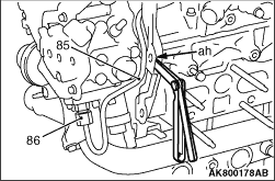
| caution |
The following operations require the intervention of a second person to support the high-pressure
fuel supply pipe (85); Using an 5.4 mm shim (During the union tightening method)
|
23.Position a 5.4 mm shim between the new high-pressure fuel supply pipe (85) and the
engine lifting eye (At "ah").
|
|
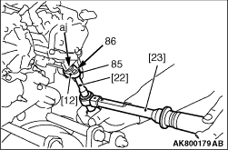
24.Method for tightening the union (86):
25.Apply a counter-torque (At "aj").
26.Pre-tightening of the high-pressure fuel supply pipe (85) onto the high-pressure fuel
pump to 22 ± 2 N·m; Using the tools [12], [22], [23].
27.Tighten to 25 ± 2 N·m; Using the tools [12], [22], [23].
|
|
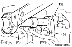
28.Method for tightening the union (94); Using the tools [12], [22], [23]:
29.Pre-tightening to 22 ± 2 N·m.
30.Tighten to 25 ± 2 N·m.
|
|
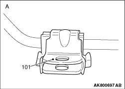
1.A: Correct fitting.
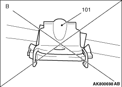
2.B: Incorrect fitting.
| caution |
The retention bracket of the high-pressure pipe (85) must
be free to rotate on the high-pressure fuel supply pipe; The retaining clip must not be closed.
|
|
|
|
1.Fit: The retaining clip fixing bolt (101).
|
|
|
3.The bolt fixing the retention bracket to 8 ± 2 N·m.
|
|
|
4.The fixing bolts of the high-pressure fuel injection common rail to 18 ± 2 N·m.
|
)
)
)
)
)
)
)
)
)
)
)
)
)
)
)
)