BASE ENGINE


CYLINDER HEAD


A cylinder head made of an aluminum alloy, which is lightweight and offers a high level of cooling efficiency, has been adopted. A pent roof combustion chamber with a center spark plug has been adopted. It has a small valve compound angle to create a compact chamber.
Cross-flow type inlet and exhaust ports have been adopted. Two inlet ports and two exhaust ports are provided independently on the right and left sides.
Four camshaft bearings are provided at the inlet and exhaust sides, respectively. The No. 4 bearing sustains the thrust load of the camshaft.

VALVE SEAT


The valve stem seals use springs with good seal performance to prevent oil draining down.
The oversize valve guides are available as spare parts: 0.3.

VALVE GUIDE


A sintered alloy material is used for the valve guides.
The three kinds of the oversize valve guides are available as spare parts: 0.05, 0.25 and 0.50.

CYLINDER HEAD GASKET


A 2.5-layer metal gasket with good sealability and heat resistance is used for the cylinder head gasket.

ROCKER COVER


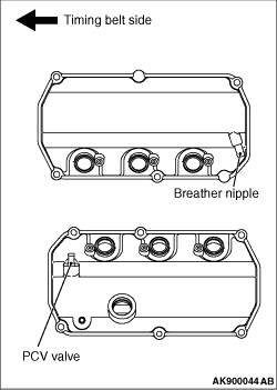
A lightweight resin material is used for the cylinder gasket cover.

CYLINDER BLOCK


An aluminum alloy material is used for the cylinder block to be lightweight.
The crankshaft journal has 4 bearings. The No.3 bearing carries the thrust load of the crankshaft.
A full Siamese type water jacket is used.
Items
Specifications
Bore mm
87.6
Bore pitch mm
98
Stroke mm
82.9

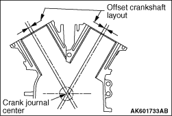
The cylinders are offset from the center of the crankshaft.

PISTON


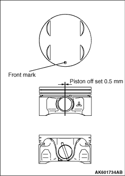
Special aluminum alloy is adopted to improve heat efficiency and achieve lower weight.
That contributes to higher engine performance and better fuel economy. Piston pinhole center is offset by 0.5 mm from piston center towards the thrust side.
Out side surface of piston skirt has striation-like finishing better oil holding ability (and superior durability against scuffing.)
Items
Specifications
Basic diameter mm
87.6
Pin hole diameter mm
22
Overall height mm
47.78

PISTON PIN


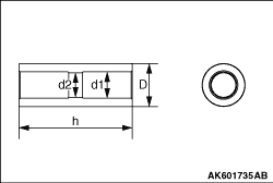
Semi-floating piston pin is adopted. Piston pin is into the small end of connecting rod so that it floats in piston.
Items
Specifications
Outer diameter (D) mm
22
Inner diameter (d1) mm
13.5
Inner diameter (d2) mm
12.5
Overall length (h) mm
58

PISTON RING


Piston ring consists of ring No.1, No. 2, and oil ring.
Items
Piston ring No.1
Piston ring No.2
Oil ring
Shape
Inside bevel, Barrel
Taper
3-piece, Barrel
Surface treatment (cylinder contact surface)
Chrome nitride (PVD)
Parkerizing + resin coating
Hard plated Parkerizing
Supplier mark
1T
2T
None

CONNECTING ROD


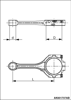
High strength carbon steel (forging) material is adopted.
Rod has "H" shaped cross section.
Big-end is lubricated through crankshaft oil passage between main journal and pin.
Items
Specifications
Small end hole diameter (d) mm
22
Big end hole diameter (D) mm
56
Center-to-center distance (L) mm
145

CONNECTING BEARING


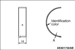
Upper and lower bearings are same parts.
This part consists of overlay (surface), copper alloy plate (middle) and steel plate (back side).
To reduce friction loss, width of connecting rod bearing is designed as short as possible composed with crankshaft journal.
Items
Specifications
Width (H) mm
14.4
Thickness (A) mm
1.5

CRANKSHAFT


A forged crankshaft has been adopted.
This crankshaft has 4-main bearings and 5-balancing weights.
Crankshaft pins are located in every 60 degrees.
Lubrication oil is lead from main journal to pin.
Timing belt sprocket and crankshaft pulley are assembled at front end.
Items
Specifications
Pin outer diameter mm
53
Journal outer diameter mm
69

CRANKSHAFT BEARING AND THRUST BEARING


Main bearing consists of aluminum alloy (surface) and steel plate (backside).
Thrust bearing, which controls axial movement of crankshaft, is assembled at No.3 journal.
Items
Specifications
Crankshaft bearing
Width mm
18.5
Thickness mm
2.0
Crankshaft thrust bearing
Thickness mm
2.0

CRANKSHAFT PULLEY


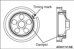
The outer ring has 6-rib for power steering pump and 4-rib for alternator and air-compressor drive belt.
Timing mark notch is applied at the flange of 4-rib side.

DRIVE PLATE


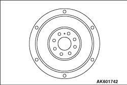
The drive plate is made of sheet metal.
The drive plate is mounted with 8 bolts.

TIMING BELT


By using the highly strengthen timing belt, the belt is narrow and long-lasting. This allows the friction to be decreased, and the engine weight to be lightweight.
By abolishing a traditional eccentric pulley, the tensioner is designed to be lightweight.
By applying the projection of the timing belt cover, the timing belt is prevented from coming off the tooth.

VALVE


The valve is made of heat resistant steel and has nitride processing on its entire surface.
Items
Inlet valve
Exhaust valve
Head diameter (D) mm
35.0
29.5
Stem diameter (d) mm
6.0
6.0
Overall length (L) mm
111.84
114.04

VALVE STEM SEAL


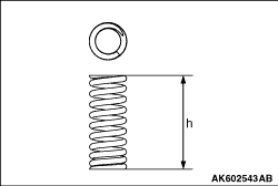
Oil is prevented from seeping down by using a good sealing spring on the valve stem seal.

VALVE SPRINGS


To prevent surging during high speed, variable pitch springs are used.
Items
Inlet valve
Exhaust valve
Free height (h) mm
63.77
59.97
Total number of windings
11.57
10.40

CAMSHAFT


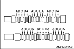
The camshaft has the two kinds of the cams, for high speed and low speed, at the inlet side.
Items
Cam height mm
A: Inlet low speed cam
37.28
B: Inlet low speed cam
36.23
C: Exhaust cam
37.84

MITSUBISHI INNOVATIVE VALVE TIMING AND LIFTING ELECTRONIC CONTROL SYSTEM (MIVEC)


MIVEC has an additional switching system on the two inlet valves in the conventional SOHC 4 valve engine. This switching system has two cams for the low mode and for the high mode keeping both valve lifts high.
In the range of the low engine speed, the flow within the valves is enhanced by the difference between the valve-lifts. Also, the stabilization of the combustion is designed for low fuel economy, low exhaust gas and high torque. At high engine speeds, the high output due to the increment in the inlet air amount is reached by increasing the open valve period and the lift.
A T-lever moves following the high lift cams and is arranged between the high lift cam and two rocker arms, in addition to the low lift cams and two rocker arms that drive the two inlet valves respectively.
In the range of the low engine speed, the low lift cam drive each valve respectively because the wing of the T-lever moves freely. At high engine speeds, the oil pressure moves the switch-over piston within the rocker arm. The T-lever reaches the rocker arm and pushes it, and then the high lift cam lifts both valves.
The cam switching is carried out when the torque produced in the low speed mode and the one produced in the high-speed mode crosses each other at an engine speed.
The oil passage is divided into two, one for the inlet rocker shaft and the other for the exhaust rocker shaft, just in front of the oil feeder control valve (OCV). Oil is always supplied to the exhaust rocker shaft.
Oil supply to the inlet rocker shaft is controlled by ON/OFF of the oil feeder control valve (OCV) and carries out the switching for the low and high lift cams.


When the OCV is in the OFF position, the switch-over piston does not operate because the switch-over oil pressure within the inlet rocker shaft is below the specified pressure, and so the wing of the T-lever does not reach the switch-over piston. Accordingly, the inlet valve is driven by the rocker arm for low lift cam.


When the OCV is in the ON position, the switch-over piston is pushed by the oil pressure because the switch-over oil pressure within the inlet rocker shaft is above the specified pressure, and so the wing of the T-lever reaches the switch-over piston. Accordingly, the inlet valve is driven by the T-lever.

OIL FEEDER CONTROL VALVE


The oil feeder control valve uses electromagnetic valve mechanism to change oil pressure to rocker arm and rocker shaft that drive MIVEC.