EXTERIOR LAMPS


Construction diagram


Specifications


Item
Headlamp assembly <Vehicles with halogen type headlamp>
High-beam W <halogen headlamp>
60 (HB3)
Low-beam W <halogen headlamp>
51 (HB4)
Position lamp W
5 (W5W)
Front turn-signal lamp W
21 (WY21W)
Headlamp assembly <Vehicles with discharge type headlamp>
High-beam / low-beam W <discharge headlamp>
35 (D2S)
Bending lamp W
55 (H11)
Position lamp W
5 (W5W)
Front turn-signal lamp W
21 (WY21W)
Front fog lamp W
55 (H11)
Rear fog lamp W
21 (W21W)
Side turn-signal lamp
Fender panel type W
5
Door mirror type
LED type
Rear combination lamp assembly
Tail/stop
LED type
Rear turn-signal W
21 (WY21W)
Tail lamp assembly
Back-up W
21 (W21W)
High-mounted stop lamp
Integrated in tailgate spoiler
LED type
Licence plate lamp W
5 (W5W)
note The brackets ( ) show the bulb type.

Headlamp manual levelling system


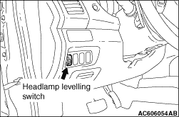
The beam direction of the headlamps changes according to the number of passengers and the amount of load. The headlamp manual levelling function is a system that allows the driver to change the direction of headlamp beam so that the drivers of oncoming cars are not dazzled by the headlamps. The headlamp levelling switch allows changing the direction in five steps: 0 to 4.

Relationship between the switch positions and the number of passengers/loads


5-seating
Passenger and load


One or two passengers
Five passengers
Five passengers and heavy loads
Driver and heavy loads
Switch position
0
1 or 2
3
4
7-seating
Passenger and load


One or two passengers
Four passengers (front seat and third seat)
Seven passengers
Seven passengers and heavy loads
Driver and heavy loads
Switch position
0
2
3
3
4
note Each switch position is for reference. In each switch position, when the headlamp beam is too high, turn the switch to one-level higher position.

Operation


1.The headlamp levelling switch increases the resistance as it is turned from 0 to 4. Turning the headlamp levelling switch changes the voltage at point A. When the headlamp levelling switch is turned from 0 to 4, the voltage at point A decreases. Upon detection of this voltage change, the headlamp levelling unit turns the motor to lower the beam direction. At this time, the resistance of the variable resistor in the headlamp assembly changes, and the voltage at point B decreases gradually. When the voltages at points A and B become equal, the headlamp levelling unit stops the motor.
2.Turning the headlamp levelling switch from 4 to 0 increases the voltage at point A, and then the headlamp levelling unit turns the motor in the direction opposite to that mentioned in Item 1, increasing the voltage at point B. When the voltages at points A and B become equal, the headlamp levelling unit stops the motor.
3.The headlamp levelling unit detects voltage changes caused by headlamp levelling switch operation, and turns the motor to change the directions of the headlamp reflectors for the adjustment of the headlamp beam direction.

Headlamp automatic levelling system


The beam direction of the headlamps (vertical angle) changes according to the number of passengers and the amount of load. The headlamp automatic levelling system is a system that automatically controls the beam direction of headlamps (up and down angle) when parking or travelling with stable vehicle attitude so that the drivers of oncoming cars and of cars driving in front are not dazzled by the headlamp beam that is directed upwards.

Operational Description


The beam direction of headlamps is automatically controlled according to driving conditions as described in the table below.
Vehicle condition
Control content
When parking
When the engine is stopped with the headlamp (low-beam) ON or when the vehicle is stopped with the headlamp (low-beam) ON and the accelerator pedal is released, the headlamp automatic levelling-ECU controls the beam direction according to the height sensor values of the change in load resulting from getting on/off of passengers or loading/unloading of loads.
When driving at a constant speed
When a vehicle starts on curb, the travelling vehicle posture changes from the posture during parking, so that the beam direction changes. To control the improper beam direction caused by such vehicle attitude change, the headlamp automatic levelling ECU controls the beam direction while travelling with stable vehicle attitude. This beam direction control while travelling with stable vehicle attitude is performed only once between a vehicle stop and the next stop. When driving is started on a gravel or rough road, the beam direction control is activated after the vehicle attitude becomes stable on a paved road.

System component and function


Parts name
Functional description
Ignition switch
Supplies power to the headlamp automatic levelling-ECU when the ignition switch is in the ON position.
Height sensor (front)
Detects the elongation/contraction of the front suspension and transmits the signal to the headlamp automatic levelling-ECU.
Height sensor (rear)
Detects the elongation/contraction of the rear suspension and transmits the signal to the headlamp automatic levelling-ECU.
Headlamp assembly (integrating headlamp automatic levelling motor)
Drives the headlamp reflector by receiving signals from the headlamp automatic levelling-ECU.
Combination meter (headlamp automatic levelling warning display)
Indicates the warning on the multi-information display when:

  • An error has occurred in the headlamp automatic levelling system.
  • The headlamp automatic levelling-ECU has not been initialised.
  • The headlamp automatic levelling motor drive test is being executed.
note When the ignition switch is turned from the LOCK (OFF) position to the ON position, the headlamp automatic levelling warning is displayed for 3 seconds to check the headlamp automatic levelling warning display for malfunction.
ABS-ECU or ASC-ECU
Transfers the vehicle travel distance information to the headlamp automatic levelling-ECU.
Engine-ECU
Transfers engine speed signals and accelerator pedal position signals to the headlamp automatic levelling-ECU.
ETACS-ECU
Transfers lighting switch position signals, all door switch ON/OFF signals, tailgate latch switch ON/OFF signals, hazard warning lamp switch ON/OFF signals, headlamp (low-beam) ON/OFF status signals, and vehicle information to the headlamp automatic levelling-ECU.
Headlamp automatic levelling-ECU
Controls the headlamp automatic levelling motor integrated in the headlamp assembly based on the signals form switches and sensors to control the beam direction according to the vehicle posture. The headlamp automatic levelling-ECU controls AFS as well. (Refer to .)
Diagnosis connector
Outputs diagnosis codes.

System block diagram


AFS (Adaptive front-lighting system)


AFS (Adaptive front-lighting system) turns the bending lamp automatically ON/OFF according to the rotation angle of the steering wheel and beams the driving direction during corning at night to support the driver. AFS control can be turned OFF by operating the AFS control switch.
note The AFS is controlled by the headlamp automatic levelling-ECU.

Operational Description


ON operation:
When all the conditions below are satisfied, the bending lamp of a side to which the steering wheel is steered turns ON.

OFF operation:
When any of the conditions below are satisfied while the bending lamp is ON, the bending lamp turns OFF.


System component and function


Parts name
Functional description
Ignition switch
Supplies power to the headlamp automatic levelling-ECU when the ignition switch is in the ON position.
AFS control switch
Transmits the AFS ON/OFF signal to headlamp automatic levelling-ECU.
Headlamp relay (LO)
Supplies the battery voltage to the headlamp automatic levelling-ECU as the power supply for the bending lamp when the headlamp relay (LO) is ON.
Steering wheel sensor
Detects the rotation angle of the steering wheel and transmits the signal to headlamp automatic levelling-ECU.
Combination meter (AFS OFF indicator lamp)
When AFS is turned OFF by the AFS control switch, turns ON the AFS OFF indicator lamp by the signal from headlamp automatic levelling-ECU to inform the driver of the AFS shutdown. In addition, when a failure has occurred in AFS, blinks the AFS OFF indicator to inform the driver of the AFS error.
Combination meter (AFS warning display)
When a failure has occurred in AFS, indicates the AFS warning on the multi-information display in the combination meter by the headlamp automatic levelling-ECU signal to inform the driver of the AFS error.
ABS-ECU or ASC-ECU
Transmits the vehicle speed signal to headlamp automatic levelling-ECU.
ETACS-ECU
Transmits the ignition switch position signal, lighting switch position signal, headlamp (low-beam/ high-beam) ON/OFF status signal, parking brake switch ON/OFF signal, shift lever position signal <M/T and TC-SST>, selector lever position signal <A/T and CVT>, and vehicle information to the headlamp automatic levelling-ECU.
Headlamp automatic levelling-ECU
According to the signals from the switches, ECUs, and steering wheel sensors, turns ON/OFF the bending lamp.
Diagnosis connector
Outputs diagnosis codes.

System block diagram