| Item 6: Transfer shift lever position (Refer to data list reference table  ). ).
|
| Q.
Is the check result normal? |
|  Intermittent malfunction (Refer to GROUP 00 - How to Cope with Intermittent
Malfunction ). Intermittent malfunction (Refer to GROUP 00 - How to Cope with Intermittent
Malfunction ).
|
| |
| Q.
Is the check result normal? |
|  Replace the transfer shift lever switch (Refer to ). Replace the transfer shift lever switch (Refer to ).
|
| |

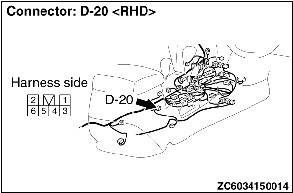
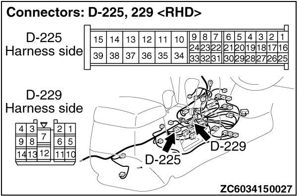
| (1)Disconnect the connector, and measure the voltage between terminal No.1 and earth at the
wiring harness side.
(2)Turn the ignition switch to the ON position.
OK: System voltage
Q.
Is the check result normal?Go to Step 6.
Go to Step 4.
|
| Check for the contact with terminals.
Q.
Is the check result normal?Go to Step 5.
Repair the defective connector.
|
| Check the power supply line for short or open circuit.
Q.
Is the check result normal?Go to Step 10.
Repair the wiring harness.
|
| (1)Disconnect transfer shift lever switch connector D-20.
(2)Turn the ignition switch to the ON position.
|
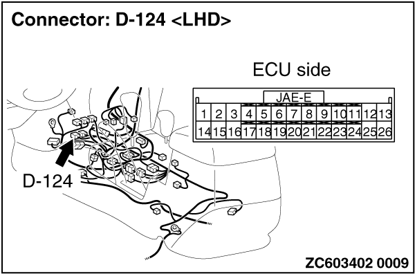
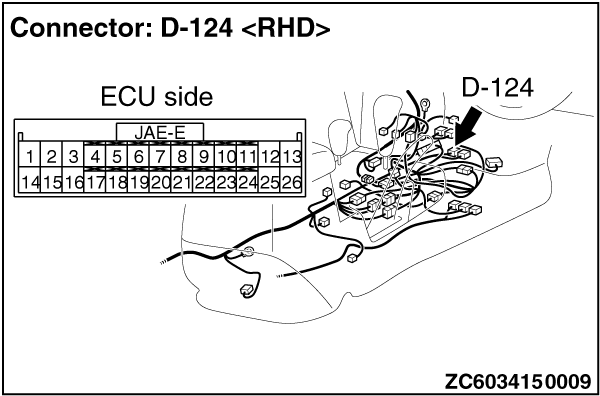
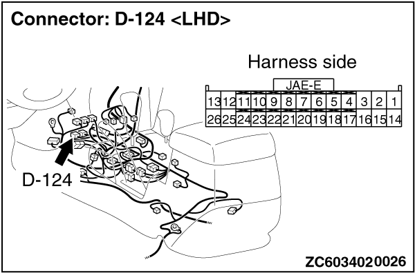
| (3)Measure the voltage between transfer-ECU connector D-124 terminal No.20 (Transfer shift
lever position: 2H) and earth. [terminal No.21 (Transfer shift lever position: 4H), terminal
No.22 (Transfer shift lever position: 4HLc), terminal No.23 (Transfer shift lever position:
4LLc) and earth].
OK: System voltage
Q.
Is the check result normal?Go to Step 9.
Go to Step 7.
|

| Check for the contact with terminals.
Q.
Is the check result normal?Go to Step 8.
Repair the defective connector.
|
| Check the output line for short or open circuit.
Q.
Is the check result normal?Go to Step 10.
Repair the wiring harness.
|
| Check for the contact with terminals.
Q.
Is the check result normal?Go to Step 10.
Repair the defective connector.
|
| Item 6: Transfer shift lever position (Refer to data list reference table ).
|
| Q.
Is the check result normal? |
| Intermittent malfunction (Refer to GROUP 00 - How to Cope with Intermittent
Malfunction ).
|
| |
| Replace the transfer-ECU.
|
| |
)
)
)
)
)
)
)
)
)
)
)