|
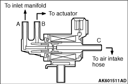
The EGR control solenoid valve is installed to the inlet manifold and controls the intake
amount of the exhaust gas from the exhaust pipe. The EGR control solenoid valve is a duty control type
solenoid valve. The nipple "A" is kept airtight and air blows between the nipple "B" and "C"
when currents are not flowing through the coil. This allows the atmospheric pressure to come in
the diaphragm and the EGR valve is closed not to take in the exhaust gas. The nipple "C" is
kept airtight and air blows between the nipple "A" and "B" when currents are flowing through
the coil. This allows the inlet manifold vacuum to come in the diaphragm and the EGR valve is
open to take in the exhaust gas. The engine ECU, the engine A/T-ECU, changes the ON duty ratio
according to the engine operation condition and controls the intake amount of the exhaust gas.
|
|
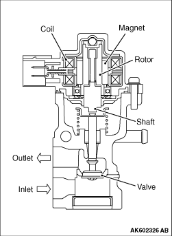
An exhaust gas recirculation valve is installed in the inlet manifold plenum.The exhaust
gas recirculation valve controls exhaust gas recirculation flow volume using the stepper motor method
and reduces exhaust gas (NOx) and fuel consumption. The exhaust gas recirculation valve drives
the stepper motor based on the signal from engine-ECU <M/T> or engine-A/T-ECU <A/T>.
When stepper motor rotor turns in clockwise or anti-clockwise direction, the shaft fitted with
a rotor and a screw expands and contracts and the movement of the shaft causes the valve to
go up and down. Thus, exhaust gas recirculation path gap is controlled minutely. The stepper
motor turns 15° per step. The stepper motor turns forward or back only up to the angle
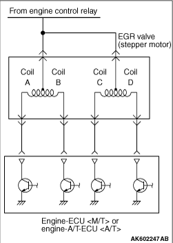
dictated by the number of pulse signals (number of steps) from the engine-ECU <M/T> or engine-A/T-ECU <A/T>. In
other words, increase and decrease of the exhaust gas recirculation flow volume depends on the
number of signals (number of steps) from engine-ECU <M/T> or engine-A/T-ECU <A/T>. Engine-ECU <M/T>
or engine-A/T-ECU <A/T> changes current flow to the 4 coils (A, B, C, D) in the stepper
motor in sequence according to the phase pattern in the following chart in order to turn the
stepper motor rotor. Open valve changes phase in order of 0 → 1 → 2 → 3 → 0.
Close valve changes phase in order of 3 → 2 → 1 → 0 → 3.
Phase number
|
Stepper motor coil
|
Coil A
|
Coil B
|
Coil C
|
Coil D
|
0
|
ON
|
OFF
|
OFF
|
ON
|
1
|
ON
|
OFF
|
ON
|
OFF
|
2
|
OFF
|
ON
|
ON
|
OFF
|
3
|
OFF
|
ON
|
OFF
|
ON
|
|
)
)
)
)
)
)