REMOVAL AND INSTALLATION <4M4>


<SHORT WHEELBASE>


Pre-removal Operation
  • Draining Fuel ().
  • Transmission Mounting Centre Member Assembly Removal (Refer to GROUP 32 - Transmission Mounting ).

Post-installation Operation
  • Transmission Mounting Centre Member Assembly Installation (Refer to GROUP 32 - Transmission Mounting ).
  • Checking for Fuel Leaks (Refer to ).
  • Refilling Fuel
  • Fuel Line Air Breeding (Refer to GROUP 13B - On-vehicle Service, Evacuation of Air from Fuel Line ).


Fuel tank removal steps


1.
Fuel tank under protector


2.
Fuel filler hose connection


3.
Fuel main hose connection


4.
Fuel return hose connection
<<A>>
>>B<<
5.
Fuel tank band
<<A>>
>>B<<
6.
Fuel filler neck breather hose connection
<<A>>
>>B<<
7.
Fuel tank vapour hose connection
<<A>>
>>B<<
8.
Fuel tank harness connector connection
<<A>>
>>B<<
9.
Fuel tank assembly


Fuel tank removal steps


10.
Fuel main hose


11.
Fuel return hose


12.
Fuel tank vapour hose


13.
Fuel hose connector


14.
Fuel tank hose


15.
Valve assembly


16.
Packing


17.
Fuel tank main hose


18.
Fuel tank return hose


19.
Fuel suction hose connection


20.
Fuel filter pipe assembly


21.
Packing


22.
Fuel tank harness
<<B>>
>>A<<
23.
Fuel tank gauge unit


24.
Packing


25.
Fuel tank


Fuel filler neck removal steps


2.
Fuel filler hose connection
<<A>>
>>B<<
6.
Fuel filler neck breather hose connection
<<A>>
>>B<<
7.
Fuel tank vapour hose connection


26.
Fuel tank cap


27.
Fuel filler neck protector


28.
Fuel filler neck


29.
Fuel filler neck gasket


30.
Fuel filler hose


31.
Fuel tank vapour hose


32.
Fuel filler neck breather hose


33.
Fuel filler neck pipe


34.
Fuel filler neck breather hose


35.
Fuel filler neck vapour hose


36.
Fuel filler neck vapour hose


37.
Fuel filler neck check valve

<LONG WHEELBASE>


Pre-removal Operation
  • Draining Fuel ().
  • Transmission Mounting Centre Member Assembly Removal (Refer to GROUP 32 - Transmission Mounting ).

Post-installation Operation
  • Transmission Mounting Centre Member Assembly Installation (Refer to GROUP 32 - Transmission Mounting ).
  • Checking for Fuel Leaks (Refer to ).
  • Refilling Fuel
  • Fuel Line Air Breeding (Refer to GROUP 13B - On-vehicle Service, Evacuation of Air from Fuel Line ).


Fuel tank removal steps


1.
Fuel tank under protector


2.
Fuel filler hose connection


3.
Fuel main hose connection


4.
Fuel return hose connection
<<A>>
>>B<<
5.
Fuel tank band, front
<<A>>
>>B<<
6.
Fuel tank band, rear
<<A>>
>>B<<
7.
Fuel filler neck breather hose connection
<<A>>
>>B<<
8.
Fuel tank vapour hose connection
<<A>>
>>B<<
9.
Fuel tank harness connector connection
<<A>>
>>B<<
10.
Fuel tank assembly


Fuel tank removal steps


11.
Fuel main hose


12.
Fuel return hose


13.
Fuel tank vapour hose


14.
Fuel hose connector


15.
Fuel tank hose


16.
Valve assembly


17.
Packing


18.
Fuel tank main hose


19.
Fuel tank return hose


20.
Fuel suction hose connection


21.
Fuel filter pipe assembly


22.
Packing


23.
Fuel tank harness
<<B>>
>>A<<
24.
Fuel tank gauge unit


25.
Packing


26.
Fuel tank


Fuel filler neck removal steps


2.
Fuel filler hose connection
<<A>>
>>B<<
7.
Fuel filler neck breather hose connection
<<A>>
>>B<<
8.
Fuel tank vapour hose connection


27.
Fuel tank cap


28.
Fuel filler neck protector


29.
Fuel filler neck


30.
Fuel filler neck gasket


31.
Fuel filler hose


32.
Fuel tank vapour hose


33.
Fuel filler neck breather hose


34.
Fuel filler neck pipe


35.
Fuel filler neck breather hose


36.
Fuel filler neck vapour hose


37.
Fuel filler neck vapour hose


38.
Fuel filler neck check valve

REMOVAL SERVICE POINTS


<<A>> FUEL TANK BAND/FUEL FILLER NECK BREATHER HOSE/FUEL TANK VAPOUR HOSE/FUEL TANK HARNESS CONNECTOR/FUEL TANK ASSEMBLY REMOVAL


1.
caution When moving the stabilizer bar to the position where it will not interfere with the fuel tank assembly removal, be careful not to damage the ball joint section of the stabilizer link.
Before removing the fuel tank assembly, remove the clamp of the stabilizer bar, and move the stabilizer bar to the position where it will not interfere with the fuel tank assembly removal. (Refer to GROUP 34 - Stabilizer Bar ).

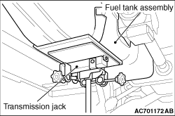
2.Support the fuel tank assembly using the transmission jack, and remove the fuel tank band and fuel tank assembly mounting nuts.
3.Using the transmission jack while taking care of the fuel filler neck breather hose, fuel tank vapour hose and the fuel tank harness, lower the fuel tank assembly until the fuel filler neck breather hose, fuel tank vapour hose and the fuel tank harness installation position over the fuel tank assembly can be checked.
4.Disconnect the fuel filler neck breather hose, fuel tank vapour hose and the fuel tank harness connector. Then, remove the fuel tank assembly.
5.After removal of the fuel tank assembly, return the stabilizer bar to the original position, and install the clamp temporarily.

<<B>> FUEL TANK GAUGE UNIT REMOVAL


caution Pay attention not to damage float of the fuel tank gauge unit when removing the fuel tank gauge unit from the fuel tank.

INSTALLATION SERVICE POINTS


>>A<< FUEL TANK GAUGE UNIT INSTALLATION


caution Pay attention not to damage and the float of the fuel tank gauge unit when installing it to the fuel tank.

>>B<< FUEL TANK ASSEMBLY/FUEL TANK HARNESS CONNECTOR/FUEL TANK VAPOUR HOSE/FUEL FILLER NECK BREATHER HOSE/FUEL TANK BAND INSTALLATION


1.
caution When moving the stabilizer bar to the position where it will not interfere with the fuel tank assembly installation, be careful not to damage the ball joint section of the stabilizer link.
Before installing the fuel tank assembly, remove the clamp of the stabilizer bar, which was installed temporarily, and move the stabilizer bar to the position where it will not interfere with the fuel tank assembly installation.

2.Place the fuel tank assembly on the transmission jack.
3.Raise the fuel tank to the position where the fuel filler neck breather hose, fuel tank vapour hose and the fuel tank harness connector can be connect.
4.Connect the fuel filler neck breather hose, fuel tank vapour hose and the fuel tank harness connector.
5.Use the transmission jack to install the fuel tank assembly to the vehicle.
6.Install the fuel tank band, and then tighten the fuel tank band mounting bolts and the fuel tank assembly mounting nuts to the specified torque and fix the fuel tank assembly.
Tightening torque: 24 ± 4 N·m
7.After removal of the fuel tank assembly, return the stabilizer bar to the original position, and install the clamp. (Refer to GROUP 34 - Stabilizer Bar ).