REMOVAL AND INSTALLATION


Pre-removal and Post-installation Operations
  • Under Skid Plate, Engine Room Under Cover Front and Engine Room Under Cover Rear Removal and Installation (Refer to GROUP 51 - Under Cover ).
  • A/T Fluid Draining and Refilling (Refer to ).
  • Transfer Oil Draining and Refilling (Refer to ).
  • Front Exhaust Pipe, Catalytic Converter and Exhaust Support Bracket Removal and Installation (Refer to GROUP 15 - Exhaust Pipe, Main Muffler and Catalytic Converter <4M4-HIGH POWER (vehicles without DPF)>, <4M4-HIGH POWER (vehicles with DPF-A/T)>).
  • Front and Rear Propeller Shaft Removal and Installation (Refer to GROUP 25 - Propeller Shaft ).
  • Radiator Condenser Tank Removal and Installation (Refer to GROUP 14 - Radiator ).
  • Air Intake Duct A Removal and Installation (Refer to GROUP 15 - Air Cleaner ).
  • Radiator Shroud Cover Removal and Installation (Refer to GROUP 14 - Radiator ).


Removal steps


1.
Tension wire connection


2.
Dynamic damper


3.
Tension wire


4.
Tension wire bracket


5.
Earth connection <Vehicles without closed type DPF>


6.
Transmission control cable connection


7.
Battery wiring harness connection


8.
Oil pan cover assembly (LH)


9.
Dust cover


10.
Heater hose connection


11.
Starter motor


12.
Drive plate connecting bolts


13.
A/T fluid cooler pipe connection
<<A>>

14.
Transmission harness connector connection


·
Support the transmission with a transmission jack


15.
Transmission mount centre member assembly (Refer to GROUP 32 - Crossmember ).


16.
Transmission mount insulator assembly


17.
Transmission harness connection

>>A<<
18.
Transmission upper connecting bolts

>>A<<
19.
Transmission lower connecting bolts

>>A<<
20.
Transmission connecting bolts
<<B>>

21.
Transmission assembly

REMOVAL SERVICE POINTS


<<A>> TRANSMISSION HARNESS CONNECTOR DISCONNECTION


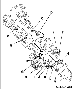
1.Lower the transmission to a position where the transmission harness connector can be disconnected, and then disconnect the connector.
2.Place the disconnected transmission harness so that it stays on the vehicle body.
Code
Connector name
A
Input shaft speed sensor
B
Inhibitor switch
C
A/T control solenoid valve assembly
D
Output shaft speed sensor
E
2WD operation detection switch
F
4LLc detection switch
G
Front propeller shaft speed sensor
H
No.3 exhaust gas temperature sensor <Closed type DPF>
I
Centre differential lock detection switch
J
4H detection switch
K
2WD/4WD detection switch
L
Shift actuator
M
Vehicle speed sensor
N
Rear propeller shaft speed sensor
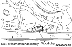
<<B>> TRANSMISSION ASSEMBLY REMOVAL


caution To prevent the engine assembly from tilting significantly when the transmission assembly is removed, place a piece of wood between the No.2 crossmember assembly and the oil pan to fix the engine assembly.

INSTALLATION SERVICE POINT


>>A<< TRANSMISSION CONNECTING BOLTS/TRANSMISSION UPPER CONNECTING BOLTS/TRANSMISSION LOWER CONNECTING BOLTS INSTALLATION


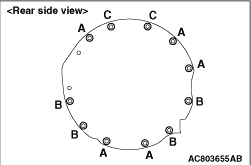
The sizes of the mounting bolts are different. So be sure not to confuse them.

Bolt
d × l mm
A
10 × 25
B
10 × 45
C
10 × 50