REMOVAL AND INSTALLATION <6G72>


Pre-removal Operation
  • Fuel Line Pressure Reduction (Refer to GROUP 13D - On-vehicle Service, Reduce Pressurized Fuel Lines ).
  • Engine Coolant Draining (Refer to GROUP 14 - On-vehicle Service, Engine Coolant Replacement ).
  • Battery and Battery Tray Removal (Refer to GROUP 54A - Battery ).
  • A/T Fluid Level Gauge and Guide Assembly <A/T> Removal (Refer to GROUP 11E - Engine Oil Pan and Strainer ).
  • Engine Oil Level Gauge and Guide Assembly Removal (Refer to GROUP 11E - Engine Oil Pan and Strainer ).
  • Air Cleaner Assembly Removal (Refer to ).
  • Throttle Body Assembly Removal (Refer to GROUP 13D - Throttle Body Assembly ).
  • EGR Valve Removal (Refer to GROUP 17 - Emission Control, EGR Valve ).
  • EGR Pipe Removal (Refer to ).
  • Fuel High-pressure Tube Removal (Refer to GROUP 11E - Engine Assembly ).

Post-installation Operation
  • Fuel High-pressure Tube Installation (Refer to GROUP 11E - Engine Assembly ).
  • EGR Pipe Installation (Refer to ).
  • EGR Valve Installation (Refer to GROUP 17 - Emission Control, EGR Valve ).
  • Throttle Body Assembly Installation (Refer to GROUP 13D - Throttle Body Assembly ).
  • Air Cleaner Assembly Installation (Refer to ).
  • Engine Oil Level Gauge and Guide Assembly Installation (Refer to GROUP 11E - Engine Oil Pan and Strainer ).
  • A/T Fluid Level Gauge and Guide Assembly <A/T> Installation (Refer to GROUP11E - Engine Oil Pan and Strainer ).
  • Battery and Battery Tray Installation (Refer to GROUP 54A - Battery ).
  • Engine Coolant Refilling (Refer to GROUP 14 - On-vehicle Service, Engine Coolant Replacement ).
  • Fuel Leak Check


Removal steps


1.
Control harness connection


2.
Earth cable connection


3.
PCV hose connection


4.
Fuel purge hose connection


5.
Free wheel clutch vacuum hose connection


6.
Purge solenoid valve, vacuum hose and vacuum pipe assembly


7.
EGR solenoid valve and vacuum hose assembly


8.
Harness bracket


9.
Manifold absolute pressure sensor


10.
O-ring


11.
Air intake fitting


12.
Air intake fitting gasket


13.
Harness bracket


14.
Detonation sensor, camshaft position sensor connector bracket


15.
Fuel injector harness connector bracket


16.
Noise condenser


17.
Water outlet fitting bracket


18.
Surge tank stay


19.
Upper inlet manifold

>>E<<
20.
Surge tank gasket


Removal steps


21.
Fuel injector harness connection
<<A>>
>>D<<
22.
Fuel delivery pipe, fuel high-pressure tube and fuel injector assembly


23.
Insulator

>>C<<
24.
O-ring


25.
Water hose connection


26.
Harness clamp

>>B<<
27.
Inlet manifold

>>A<<
28.
Inlet manifold gasket

REMOVAL SERVICE POINT


<<A>> FUEL DELIVERY PIPE, FUEL HIGH-PRESSURE TUBE AND FUEL INJECTOR ASSEMBLY REMOVAL


caution Do not drop the fuel injector.
Remove the fuel delivery pipe and fuel high-pressure tube with the fuel injector assembly attached to it.

INSTALLATION SERVICE POINTS


>>A<< INLET MANIFOLD GASKET INSTALLATION


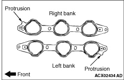
Install the inlet manifold gasket with the protrusions in the position illustrated.

>>B<< INLET MANIFOLD INSTALLATION


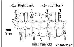
Tighten the inlet manifold mounting nuts by the following procedure.
Order
Mounting nuts
Tightening torque
1st
Right bank nuts
6.5 ± 1.0 N·m
2nd
Left bank nuts
22 ± 1 N·m
3rd
Right bank nuts
22 ± 1 N·m
4th
Left bank nuts
22 ± 1 N·m
5th
Right bank nuts
22 ± 1 N·m

>>C<< O-RING INSTALLATION


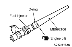
1.Apply a drop of new engine oil to the O-ring.

2.Using special tool O-ring installer (MB992106), install the O-ring to the fuel injector paying attention to avoid damage to the O-ring.

>>D<< FUEL DELIVERY PIPE, FUEL HIGH-PRESSURE TUBE AND FUEL INJECTOR ASSEMBLY INSTALLATION


1.
caution Do not let the engine oil get into the inlet manifold.
Apply a small amount of new engine oil to the O-ring at the tip of the fuel injector.
2.
caution When installing the fuel delivery pipe, fuel high-pressure tube and fuel injector assembly to the inlet manifold, take care not to damage the O-ring at the tip of the fuel injector assembly.
Install the fuel delivery pipe, fuel high-pressure tube and fuel injector assembly to the inlet manifold.

>>E<< SURGE TANK GASKET INSTALLATION


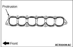
Install the surge tank gasket with the protrusions in the position illustrated.