REMOVAL AND INSTALLATION


Pre-removal Operation
  • Fuel Line Pressure Reduction (Refer to GROUP 13D - On-vehicle Service, Reduce Pressurized Fuel Lines ).
  • Under Skid Plate and Engine Room Under Cover (Front) Removal (Refer to GROUP 51 - Under Cover ).
  • Engine Oil Draining (Refer to GROUP 12 - On-vehicle Service, Engine Oil Replacement ).
  • Engine Coolant Draining (Refer to GROUP 14 - On-vehicle Service, Engine Coolant Replacement ).
  • Inlet Manifold Removal (Refer to GROUP 15 - Inlet Manifold ).
  • Ignition Coil Removal (Refer to GROUP 16 - Ignition System, Ignition Coil ).
  • Timing Belt Removal (Refer to ).
  • Front Exhaust Pipe or Front Catalytic Converter Removal (Refer to GROUP 15 - Exhaust Pipe, Main Muffler and Catalytic Converter ).

Post-installation Operation
  • Front Exhaust Pipe or Front Catalytic Converter Installation (Refer to GROUP 15 - Exhaust Pipe, Main Muffler and Catalytic Converter ).
  • Timing Belt Installation (Refer to ).
  • Ignition Coil Installation (Refer to GROUP 16 - Ignition System, Ignition Coil ).
  • Inlet Manifold Installation (Refer to GROUP 15 - Inlet Manifold ).
  • Engine Coolant Refilling (Refer to GROUP 14 - On-vehicle Service, Engine Coolant Replacement ).
  • Engine Oil Refilling (Refer to GROUP 12 - On-vehicle Service, Engine Oil Replacement ).
  • Under Skid Plate and Engine Room Under Cover (Front) Installation (Refer to GROUP 51 - Under Cover ).
  • Fuel Leak Check


Cylinder head gasket (L.H.) removal steps


1.
Blow-by hose


·
Cooling water outlet pipe, water pump inlet pipe and Cylinder head water by-pass pipe (Refer to GROUP 14 - Water Hose and Water Pipe ).


2.
Camshaft position sensor connector


3.
Rocker cover assembly <left bank>


4.
Rocker cover gasket
<<A>>
>>B<<
5.
Left bank cylinder head assembly

>>A<<
6.
Cylinder head gasket


Cylinder head gasket (R.H.) removal steps


1.
Blow-by hose


·
Cooling water outlet pipe, water pump inlet pipe and Cylinder head water by-pass pipe (Refer to GROUP 14 - Water Hose and Water Pipe ).


7.
Rocker cover assembly <right bank>


8.
Rocker cover gasket
<<A>>
>>B<<
9.
Right bank cylinder head assembly

>>A<<
10.
Cylinder head gasket

REMOVAL SERVICE POINT


<<A>> CYLINDER HEAD ASSEMBLY REMOVAL


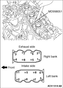
Using special tool head bolt wrench (MD998051), loosen the cylinder head bolts in two or three steps in the order of the numbers shown in the illustration.

INSTALLATION SERVICE POINTS


>>A<< CYLINDER HEAD GASKET INSTALLATION


1.
caution Do not allow any foreign materials get into the coolant passages, oil passages and cylinder.
Degrease the cylinder head gasket mounting surface.

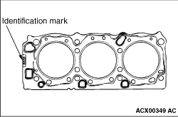
2.Assemble to the cylinder block so the cylinder head gasket identification mark is at the top surface.

>>B<< CYLINDER HEAD ASSEMBLY INSTALLATION


1.
caution Be careful that no foreign material gets into the cylinder, coolant passages or oil passages. Engine damage may result.
Use a scraper to clean the gasket surface of the cylinder head assembly.

2.
caution 
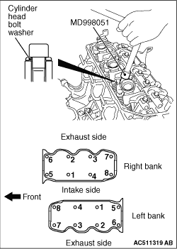
Install the head bolt washers with the bevelled side facing upwards as shown in the illustration.
Use special tool head bolt wrench (MD998051) to tighten the cylinder head bolts as follows:
(1) Tighten the cylinder head bolts to 108 ± 5 N·m in the order shown.
(2) Loosen the bolts fully in the reverse order of that shown.
(3) Tighten the cylinder head bolts to 108 ± 5 N·m in the order shown.