|
|
1.With the hose installed, remove the power steering oil pump assembly from the bracket.
|
|
|
2.After removing the power steering oil pump assembly, secure it with a cord in the location where the removal and installation of the timing belt cannot be hindered.
|
|
|
1.With the hose installed, remove the A/C compressor and clutch assembly from the bracket.
|
|
|
2.After removing the A/C compressor and clutch assembly, secure it with a cord in the location where the removal and installation of the timing belt cannot be hindered.
|
|
1.
| caution |
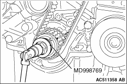
Never turn the crankshaft anti-clockwise.
|
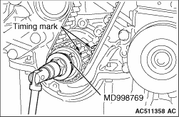
Use special tool crankshaft sprocket spacer (MD998769), turn the crankshaft clockwise to align each timing mark and to set the No.1 cylinder to compression top dead centre.
2.If the timing belt is to be reused, chalk an arrow on the flat side of the belt, indicating the clockwise direction.
3.Loosen the timing belt tensioner pulley mounting bolt, then remove the timing belt.
|
|
|
If the timing belt tensioner adjuster pushrod remains fully extended, set according to the following procedure.
|
|
1.
| caution |
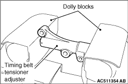
Place the timing belt tensioner adjuster perpendicular to the jaws of the vice.
|
Place two dolly blocks in a vice as shown in the illustration, and then place the timing belt tensioner adjuster in the vice.
|
|
2.
| caution |
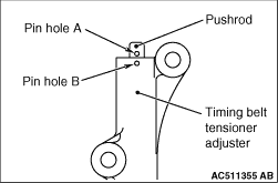
Never compress the pushrod too fast, or it may be damaged.
|
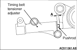
Slowly compress the pushrod of the timing belt tensioner adjuster until pin hole A in the pushrod is aligned with pin hole B in the cylinder.
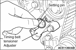
3.Insert the setting pin into the pin holes once they are aligned.
| note |
If replacing the timing belt tensioner adjuster, the pin will already be inserted into the pin holes of the new part.
|
4.
| caution |
Do not remove the setting pin from the timing belt tensioner adjuster.
|
Install the timing belt tensioner adjuster to the engine.
|
|
1.
| caution |
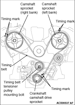
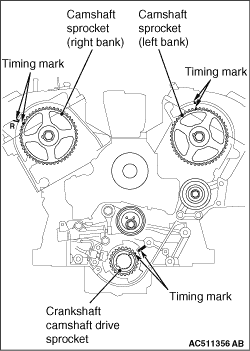
Align the timing mark of camshaft sprocket on the right bank side with the timing mark on the "R" mark side of the cylinder head.
|
Align the timing marks on the camshaft sprockets with those on the rocker cover and the timing mark on the crankshaft camshaft drive sprocket with that on the engine block as shown in the illustration.
|
|
2.
| caution |
- Align the timing mark of camshaft sprocket on the right bank side with the timing mark on the "R" mark side of the cylinder head.
- The camshaft sprocket (right bank) can turn easily due to the spring force applied, so be careful not to get your fingers caught.
|
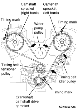
Install the timing belt by the following procedure so that there is no deflection in the timing belt between each sprocket and pulley.
(1)
Crankshaft camshaft drive sprocket
(2)
Timing belt idler pulley
(3)
Camshaft sprocket (Left bank)
(4)
Water pump pulley
(5)
Camshaft sprocket (Right bank)
(6)
Timing belt tensioner pulley
3.Turn the camshaft sprocket (Right bank) anti-clockwise until the tension side of the timing belt is firmly stretched. Check all the timing marks again.
|
|
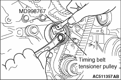
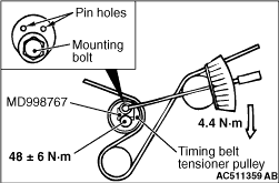
4.Use special tool tensioner wrench (MD998767) to push the timing belt tensioner pulley into the timing belt, then temporarily tighten the mounting bolt.
|
|
5.Use special tool crankshaft sprocket spacer (MD998769) to turn the crankshaft 1/4 turn anti-clockwise, then turn it again clockwise until the timing marks are aligned.
|
|
6.
| caution |
When tightening the mounting bolt, be careful that the timing belt tensioner pulley does not turn with the bolt.
|
Loosen the mounting bolt of the timing belt tensioner pulley. Use special tool (MD998767) and a torque wrench to apply the tension torque to the timing belt as shown in the illustration. Then tighten the mounting bolt to the specified torque.
Standard value: 4.4 N·m <Timing belt tension torque>
Tightening torque: 48 ± 6 N·m
|
|
7.Remove the setting pin that has been inserted into the timing belt tensioner adjuster.
8.Turn the crankshaft clockwise twice to align the timing marks.
|
|
9.Wait for at least five minutes, then check that the timing belt tensioner adjuster pushrod extends within the standard value range.
Standard value (A): 4.8 - 5.5 mm
10.If not, repeat the operation in steps 1 to 8 above.
11.Check again that the timing marks of the sprockets are aligned.
|
|
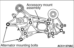
Install the bolts to the shown positions, and tighten them to the specified torque.
|
|
Bolt (symbol)
|
Diameter × length mm
|
Tightening torque N·m
|
A
|
10 × 100
|
41 ± 8
|
B
|
10 × 30
|
41 ± 8
|
C
|
10 × 100
|
44 ± 10
|
D
|
12 × 100
|
74 ± 9
|
|
|
 ).
).)
)
)
)
)
)
)
)
)
)
)
)
)
)