|
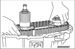
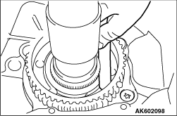
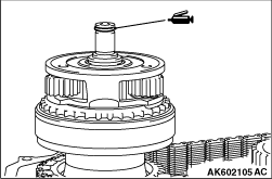
Remove the chain, front output shaft and sun gear as a set from the transfer case.
|
|
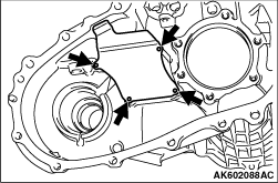
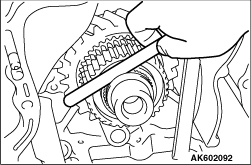
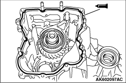
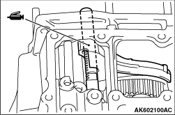
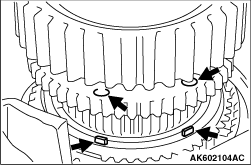
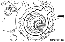
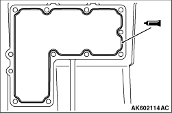
Unstake the positions shown in the illustration to remove the oil pool cover.
|
|
|
Spacer selection for adjustment of countershaft gear axial play. (Refer to adjustment
of transfer - spacer selection for adjustment of countershaft gear axial play  ) )
|
|
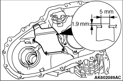
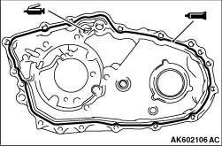
Install the oil pool cover on a new transfer case. Stake the projecting portions of the
transfer so that the dimensions will be as illustrated.
|
|
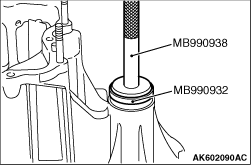
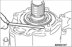
1.Using the special tools, install the oil seal.
- Installer bar (MB990938)
- Installer adapter (MB990932)
2.Apply the specified grease to the lip of oil seal.
Specified lubricant:
Mitsubishi Part No. 0101011 or equivalent
|
|
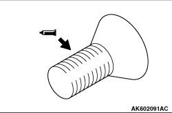
1.Apply the specified sealant to the threads.
Specified sealant:
3M™ STUD locking No. 4170 or equivalent
| note |
The new bolt does not require sealant application as it is precoated with sealant.
|
|
|
1.Select a proper snap ring so that the axial play of the H-L clutch hub will have the standard
value, and install the snap ring on the transfer drive shaft.
Standard value: 0 - 0.08 mm
(For H-L clutch hub axial play)
|
|
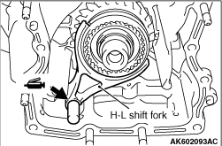
1.Apply the specified grease to the H-L shift fork shaft inserting portion, and install
the H-L shift fork and H-L clutch sleeve in combined state in the transfer case.
Specified lubricant:
Mitsubishi Part No. 0101011 or equivalent
|
|
|
Install the previously selected spacer (Refer to ADJUSTMENT BEFORE REASSEMBLY).
|
|
1.Apply the specified grease to the illustrated position of the H-L shift rail inserting
portion of the transfer case plate.
Specified lubricant:
Mitsubishi Part No. 0101011 or equivalent
|
|
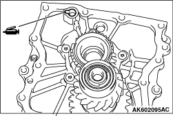
2.Face the notched portion of the input gear in the illustrated direction (in the direction
of the countershaft gear bearing hole).
|
|
3.
| caution |
Completely degrease the FIPG-applied surface so that water and oil including
the old sealant cannot adhere to the surface coated with the sealant. Never touch the degreased
surface by hand.
|
Apply the specified sealant to the transfer case.
Specified sealant:
Mitsubishi Part No. MD997740 or equivalent
4.
| caution |
If the sub gear does not readily come in mesh with the countershaft gear,
rote the transfer drive shaft, etc. to securely engage it.
|
While making sure that the notched portion of the input gear positioned in Step 2 is in
alignment with the gear portion of the countershaft, install the transfer case palate.
|
|
Select a proper snap ring so that the axial play of the differential lock hub will have
standard value, and install it on the transfer drive shaft.
Standard value: 0 - 0.08 mm
(For differential lock hub axial play)
|
|
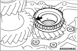
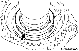
Install the steel ball in the illustrated position of the transfer drive shaft and install
the spacer with its oil groove toward the chain cover.
|
|
Apply the specified grease to the 2-4WD shift fork shaft inserting position and install
the 2-4WD shift fork and 2-4WD clutch sleeve in combined state in the transfer case.
Specified lubricant:
Mitsubishi Part No. 0101011 or equivalent
|
|
1.Install the 2-4WD clutch hub on the sun gear.
2.Select the proper snap ring so that the end of play of the 2-4WD clutch hub will have
the standard value, and install it on the sun gear.
Standard value: 0 - 0.08 mm
(For 2-4WD clutch hub axial play)
|
|
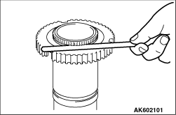
1.Combine the synchronizer outer ring, synchronizer cone and synchronizer inner ring, press
then against the drive sprocket, and measure the dimension shown in the illustration.
Limit: 0.3 mm
(For clearance between synchronizer outer ring and drive sprocket)
2.If the dimension is out of the limit value, replace them with a synchronizer ring
set.
3.Apply gear oil to the synchronizer outer ring and synchronizer inner ring.
|
|
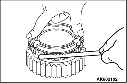
4.Line up the notched portion of the 2-4WD clutch hub with the projecting portion of the
synchronizer ring and install the ring on the 2-4WD clutch hub.
|
|
1.Set the chain in mesh with the drive sprocket and front output shaft sprocket and
install them in the transfer case.
|
|
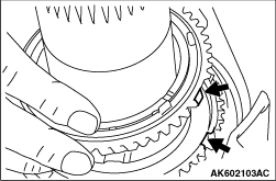
2.Install the drive sprocket so that its illustrated holes will mach the projecting portions
of the synchronizer cone.
|
|
Specified lubricant:
Mitsubishi Part No. 0101011 or equivalent
|
|
1.Apply the specified grease to the indicated 2-4WD shift rail inserting portion.
Specified lubricant:
Mitsubishi Part No. 0101011 or equivalent
2.
| caution |
Completely degrease the FIPG-applied surface so that water and oil including
the old sealant cannot adhere to the surface coated with the sealant. Never touch the degreased
surface by hand.
|
Apply the specified sealant to the illustration of the chain cover.
Specified sealant:
Mitsubishi Part No. MD997740 or equivalent
|
|
1.Install the snap ring in the bearing groove of the rear output shaft.
2.With the rear output shaft pressed against the chain cover, measure the clearance
between the chain cover and snap ring.
3.Select a snap ring whose thickness is the dimension of the measured clearance plus
the standard value.
Standard value: 0.12 - 0.24 mm
(For rear output shaft preload)
4.Remove the snap ring from the bearing groove of the rear output shaft, install the
selected snap ring, and reinstall the removed snap ring in the bearing groove of the rear output shaft.
|
|
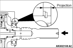
1.With the output shaft pressed toward the chain cover, measure the projection of the
bearing from the chain cover.
|
|
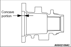
2.Measure the dimension of the rear cover concave portion at the illustrated position.
Standard value: 0 - 0.12 mm
(For rear output shaft axial play)
|
|
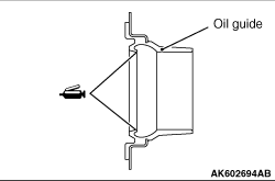
Apply specified grease to the lip of the oil seal.
Specified lubricant:
Mitsubishi Part No. 0101011 or equivalent
|
|
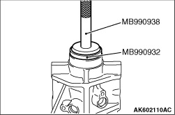
Using the special tools, install the oil seal in the rear cover.
- Installer bar (MB990938)
- Installer adapter (MB990932)
|
|
Apply the specified sealant to the illustration of the chain cover.
Specified sealant:
Mitsubishi Part No. MD997740 or equivalent
|
|
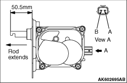
1.Contact a 12 voltage power supply across the terminals of the actuator connector in a
polarity appropriate for causing the actuator motor to move in the rod extending direction or retracting
direction until the amount of extension of the rod is as indicated in the drawing.
Terminal A
|
Terminal B
|
Rod movement
|
Power supply (+)
|
Power supply (-)
|
Extension
|
Power supply (-)
|
Power supply (+)
|
Retraction
|
|
|
2.Apply the specified grease to the O-ring.
Specified lubricant:
Mitsubishi Part No. 0101011 or equivalent
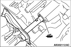
3.Combine the main shift rail key with actuator key and insert them in the transfer
case.
|
|
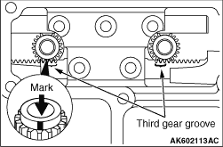
Install the shift rail drive gear with its marked tooth in mesh with the third gear groove
of the each shift rail.
|
|
Apply specified sealant to the illustrated position of the control housing.
Specified sealant:
Mitsubishi Part No. MD997740 or equivalent
|
|
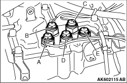
Install the switches as illustrated.
Mounting Position
|
Switch Name
|
Tube colour
|
Connector colour
|
A
|
2WD/4WD switch
|
Blue
|
Black
|
B
|
4LLC switch
|
Black
|
Brown
|
C
|
2WD switch
|
Black
|
Black
|
D
|
4H switch
|
Green
|
White
|
E
|
Centre differential lock switch
|
Blue
|
Brown
|
|
)
)
)
)
)
)
)
)
)
)
)
)
)
)
)
)
)
)
)
)
)
)
)
)
)
)
)
)
)
)
)
)
)