REMOVAL AND INSTALLATION


warning
  • Never attempt to disassemble or repair the air bag modules or clock spring. If faulty, replace it.
  • Do not drop the air bag modules or clock spring or allow contact with water, grease or oil. Replace it if a dent, crack, deformation or rust is detected.
  • The air bag modules should be stored on a flat surface is facing upward. Do not place anything on top of it.
  • Do not expose the air bag modules to temperatures over 93°C.
  • When the driver’s and passenger’s (front) air bags have been deployed, replace the driver’s and passenger’s (front) air bag modules with new ones. Also, check the clock spring, and replace with a new part if there is an abnormality.
  • Wear gloves and safety glasses when handling air bags that have already deployed.
  • An non-deployed air bag module should only be disposed of in accordance with the procedures (Refer to ).

DRIVER’S AIR BAG MODULE AND CLOCK SPRING


Pre-removal Operation
  • Check that the front wheels are at the straight ahead position.


Driver’s air bag module removal steps
<<A>>

1.
Negative battery cable connection
<<B>>

2.
Cover


3.
Horn connector connection
<<C>>

4.
Driver’s air bag module connector connection
<<D>>

5.
Driver’s air bag module


Clock spring removal steps
<<A>>

1.
Negative battery cable connection
<<B>>

2.
Cover


3.
Horn connector connection
<<C>>

4.
Driver’s air bag module connector connection
<<D>>

5.
Driver’s air bag module
<<E>>

6.
Steering wheel assembly


·
Lower, upper column cover (Refer to GROUP 37, Steering column and shaft assembly .)
<<F>>

7.
Clock spring


Driver’s air bag module installation steps

>>A<<
·
Pre-installation inspection


>>C<<
5.
Driver’s air bag module

>>D<<
4.
Driver’s air bag module connector connection

>>D<<
3.
Horn connector connection


2.
Cover


1.
Negative battery cable connection

>>E<<
·
Post-installation inspection


Clock spring installation steps

>>A<<
·
Pre-installation inspection

>>B<<
7.
Clock spring


·
Lower, upper column cover (Refer to GROUP 37, Steering column and shaft assembly .)

>>C<<
6.
Steering wheel assembly

>>C<<
5.
Driver’s air bag module

>>D<<
4.
Driver’s air bag module connector connection

>>D<<
3.
Horn connector connection


2.
Cover


1.
Negative battery cable connection

>>E<<
·
Post-installation inspection

PASSENGER’S (FRONT) AIR BAG MODULE


Removal steps
<<A>>

1.
Negative battery cable connection
<<G>>

2.
Passenger’s (front) air bag module connector connection


·
Distribution duct (Refer to GROUP 52A, Instrument panel .)


3.
Passenger’s side bracket
<<H>>

4.
Passenger’s (front) air bag module


Installation steps

>>A<<
·
Pre-installation inspection


4.
Passenger’s (front) air bag module


3.
Passenger’s side bracket


·
Distribution duct (Refer to GROUP 52A, Instrument panel .)


2.
Passenger’s (front) air bag module connector connection


1.
Negative battery cable connection

>>E<<
·
Post-installation inspection

REMOVAL SERVICE POINTS


<<A>> NEGATIVE BATTERY CABLE DISCONNECTION


danger Wait at least 60 seconds after disconnecting the battery cable before doing any further work. (Refer to ).

Disconnect the negative battery cable from the battery and tape the terminal to prevent accidental connection and air bag(s) deployment.

<<B>> COVER REMOVAL


Insert the special tool ornament remover (MB990784) as shown in the illustration to remove the cover.

<<C>> DRIVER’S AIR BAG MODULE CONNECTOR DISCONNECTION


Slide the outer housing of the driver’s air bag module connector in the arrow direction shown, and disconnect the connector.

<<D>> DRIVER’S AIR BAG MODULE REMOVAL


warning
  • Never use an electric tester to diagnose the air bag module circuit. Never attempt to disassemble the air bag module.
  • The removed driver’s air bag module should be stored in a clean, dry place with the deployment surface facing up.

<<E>> STEERING WHEEL ASSEMBLY REMOVAL


1.
caution Use the special tool to remove the steering wheel since the steering column collision absorbing mechanism may be damaged.
Position the steering wheel in a straight ahead direction.

2.Use special tool steering linkage puller (MB990803) to remove the steering wheel assembly as shown.

<<F>> CLOCK SPRING REMOVAL


warning The removed clock spring should be stored in a clean, dry place.

<<G>> PASSENGER’S (FRONT) AIR BAG MODULE CONNECTOR DISCONNECTION


Slide the outer housing of the instrument panel wiring connector in the arrow direction shown, and disconnect the connector.

<<H>> PASSENGER’S (FRONT) AIR BAG MODULE REMOVAL


warning
  • Never use an electric tester to diagnose the air bag module circuit. Never attempt to disassemble the air bag module.
  • The removed passenger’s (front) air bag module should be stored in a clean, dry place with the deployment surface facing up.

Insert a flat-tipped screwdriver or similar tool to the location shown in the figure. After disengaging the tabs, remove the front passenger’s (front) air bag module.

INSTALLATION SERVICE POINTS


>>A<< PRE-INSTALLATION INSPECTION


1.When installing the new air bag modules and clock spring, refer to “INSPECTION” ().
note Even when installing a new air bag module or clock spring, perform an inspection before the installation.
2.
caution To prevent damage to M.U.T.-III, always turn the ignition switch to the "LOCK" (OFF) position before connecting or disconnecting M.U.T.-III.
Connect M.U.T.-III to the diagnosis connector.
3.Turn the ignition switch to the “ON” position.
4.Check DTCs using M.U.T.-III to ensure entire SRS operates properly.
At this time, check that no diagnosis code except B1401, B1411, B1481 and B1491 are set.
5.
danger Wait at least 60 seconds after disconnecting the battery cable before doing any further work (Refer to ).
Turn the ignition switch to the "LOCK" (OFF) position. Disconnect the negative battery cable and tape the terminal to prevent accidental connection and air bags deployment.

>>B<< CLOCK SPRING INSTALLATION


1.Check that the front wheels are at the straight-ahead position.

2.
caution
  • If the centre of the clock spring is not correctly aligned, the steering wheel may not be turned fully or the cable inside the clock spring may be broken, causing the SRS air bag to be inoperative or operated incorrectly.
  • When aligning the clock spring neutral position mark, perform with the clock spring independently. If performed with the steering wheel sensor installed, the steering wheel sensor may be damaged.
Align the mating marks of the clock spring.
<Alignment of mating marks>
(1) Turn the clock spring clockwise fully.
(2) Turn the clock spring anti-clockwise approximately three and 1/2 turns to align the mating marks.
(3) Check that the white roller is visible from the window for checking the neutral point with the mating marks being aligned.
note If the white roller cannot be seen or black roller can be seen, the neutral point is not aligned correctly.
(4) Install the clock spring to the column switch.

>>C<< STEERING WHEEL ASSEMBLY/DRIVER’S AIR BAG MODULE ASSEMBLY INSTALLATION


1.
caution When installing the steering wheel and driver’s air bag module, ensure that the harness of the clock spring does not become caught or tangled.
Before installing the steering wheel and driver’s air bag module, turn the vehicle’s front wheels to the straight-ahead position and align the mating marks of the clock spring.
2.After securing the steering wheel, turn the steering wheel all the way in both directions to confirm that the steering wheel rotation is normal.

>>D<< DRIVER’S AIR BAG MODULE CONNECTOR CONNECTION / HORN CONNECTOR CONNECTION


Connect the connector securely and route the harnesses not to lie off the cover hole.

>>E<< POST-INSTALLATION INSPECTION


1.Reconnect the negative battery cable.
2.Turn the ignition switch to “ON” position.

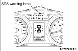
3.Does the SRS warning lamp illuminate for about 7 seconds, and go out?
4.If no, refer to troubleshooting (Refer to ).