REMOVAL AND INSTALLATION


Pre-removal and Post-installation Operation
  • Rear Splash Shield (LH) Removal and Installation (Refer to GROUP 42 - Splash Shield ).


Fuel tank removal steps


1.
Fuel filler hose connection


2.
Vapour hose connection


3.
Levelling hose connection


4.
Fuel return pipe connection


5.
Fuel main pipe connection
<<A>>
>>A<<
6.
Self-locking nut
<<A>>

7.
Fuel gauge unit connector and harness clamp
<<A>>

8.
Fuel tank assembly


9.
Fuel return hose


10.
Fuel main hose


11.
Fuel gauge unit


12.
Packing


13.
Front lower protector


14.
Fuel tank


Fuel filler neck removal steps


15.
Fuel filler hose


16.
Vapour hose


17.
Levelling hose


18.
Fuel filler cap


19.
Fuel filler neck


20.
Packing

REMOVAL SERVICE POINT


<<A>> SELF-LOCKING NUT/FUEL GAUGE UNIT CONNECTOR AND HARNESS CLAMP/FUEL TANK ASSEMBLY REMOVAL


caution Be careful not to open circuit in the harness when removing the fuel tank assembly.

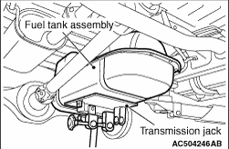
1.Support the fuel tank assembly using the transmission jack, and remove self-locking nuts.
2.Using the transmission jack while taking care of the fuel harness, lower the fuel tank assembly until the fuel harness installation position over the fuel tank assembly can be checked.
3.Disconnect fuel gauge unit connector, and harness clamp. Then, remove the fuel tank assembly.
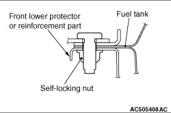
INSTALLATION SERVICE POINT


>>A<< SELF-LOCKING NUT INSTALLATION


caution When tightening the self-locking nut, be careful not to let the nut touch the bent part of the reinforcement of the fuel lower protector and the fuel tank.