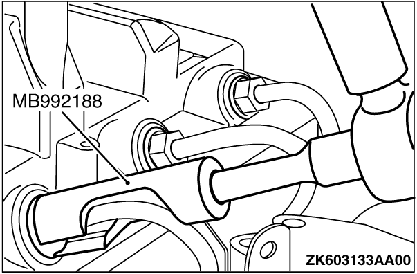
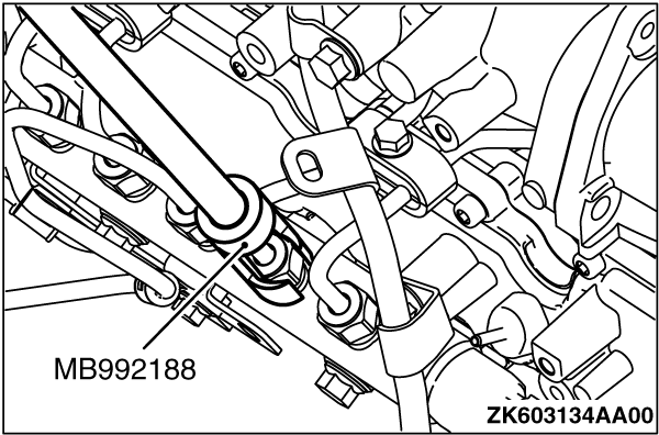
| Using special tool Fuel injection pipe wrench (MB992188), remove the fuel injection pipe
assembly No.1 to No.4.
|
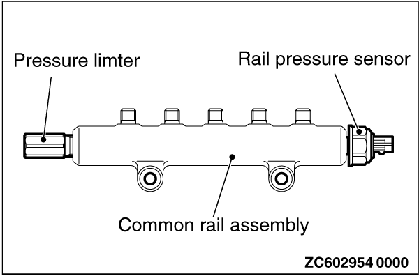
| | caution |
- When operating, do not support the common rail assembly by holding the rail
pressure limiter and the pressure sensor at both ends.
- Before the installation, make sure that there is no foreign object or rust to the
thread and to the high-pressure pipe sheet surface.
|
|
| 1.
Tighten the support bolts to the specified torque.
Tightening torque: 30.0 ± 1.5 N·m
|
| 2.
Install the gasket, injector assembly and pivot boss
|
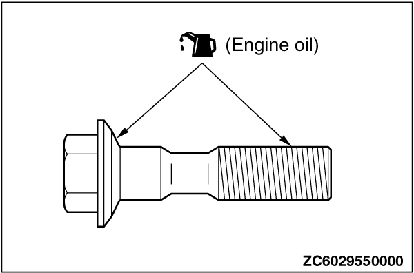
| 3.
Apply the engine oil to the bearing surface and thread of injector holder bolts.
4.
Temporarily fix the injector supporters.
5.
Install the gaskets to the fuel leakage pipe assembly.
6.
Tighten the eye bolts at the Injector assembly side to the specified torque.
Tightening torque: 15 ± 2 N·m
7.
Tighten the eye bolt at the cylinder head side to the specified torque.
Tightening torque: 15 ± 2 N·m
8.
Tighten the fuel leakage pipe assembly mounting bolt to the specified torque.
Tightening torque: 24 ± 3 N·m
|
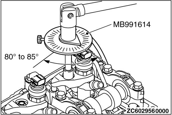
| 9.
Tighten the injector holder bolts according to the following procedure.
(1)Tighten the Injector holder bolts to 10 ± 1 N·m.
(2) | | caution |
- If the bolt is tightened less than the specified
lower limit of 80 degree angle, the bolt may become loose. Be sure to tighten correctly.
- If the bolt is tightened in excess of the specified upper limit of 85 degree angle,
loosen the bolt completely and repeat the entire procedures.
|
|
Using special tool angle gauge (MB991614), tighten the Injector supporter mounting bolts
in the illustrated sequence by a further 80 to 85 degree angle.
|
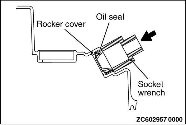
| 1.
Using a proper socket wrench, the oil seal is pressed and fit into the rocker cover.
|
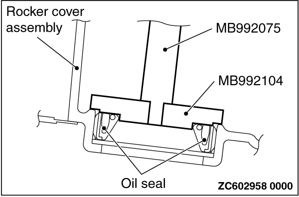
| Use special tools oil seal installer (MB992104) and handle (MB992075) to press-fit the
oil seal.
|
| 1.
Install and temporarily fix the gaskets to the fuel return A pipe assembly.
|
| 2.
Using the eye bolt, tighten the cylinder head side of fuel return A pipe assembly
to the specified torque.
Tightening torque: 20 ± 2 N·m
|

| 3.
| caution |
- When operating, do not support the common rail assembly by holding the rail
pressure limiter and the pressure sensor at both ends.
- Before the installation, make sure that there is no foreign object or rust to the
thread and to the high-pressure pipe sheet surface.
|
Temporarily fix the common rail assembly.
4.
Temporarily fix from the fuel injection No. 1 pipe assembly to fuel injection No.
4 pipe assembly.
|
| 5.
Using special tool fuel injection pipe wrench (MB992188), install the fuel injection pipe
assembly No.1 to No.4.
Tighten the fuel injection pipe assembly No.1 to No.4 to the specified torque.
Tightening torque: 35 ± 5 N·m
| note | When there is a fear that a bruise is put, wind sealing tape around the fuel pipe, to
prevent damage.
|
|
| 6.
Using the special tool, install the fuel injection pipe assembly No.1 to No.4.
Tighten the fuel injection pipe assembly No.1 to No.4 to the specified to torque of 35 ± 5
N·m at common rail side.
Tightening torque: 35 ± 5 N·m
| note | When there is a fear that a bruise is put, wind sealing tape around the fuel pipe, to
prevent damage.
|
7.
Using the eye bolt, tighten the common rail assembly side of fuel return A pipe assembly
to the specified torque.
Tightening torque: 20 ± 2 N·m
8.
Tighten the common rail assembly mounting bolt to the specified torque.
Tightening torque: 24 ± 4 N·m
9.
Tighten the bolt of the inlet manifold assembly installation point of the fuel return
A pipe assembly to the specified torque.
Tightening torque: 24 ± 4 N·m
10.
Install the fuel pipe bracket.
11.
Tighten the bolt of the fuel pipe bracket installation point of the fuel return A
pipe assembly to the specified torque.
Tightening torque: 10 ± 2 N·m
12.
Install the air inlet pipe (Refer to GROUP 15 - Inlet Manifold  ). ).
13.
Install the fuel supply pump pipe assembly.
14.
Tighten the bolt of the fuel supply pump pipe assembly to the specified torque.
Tightening torque: 35 ± 5 N·m
|
)
)
)
)
)
)
)
)
)
)