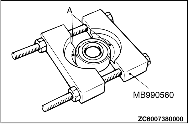
| 1.
After special tool bearing remover (MB990560) has been installed as shown, tighten the
nut of special tool MB990560 until portion "A" of special tool MB990560 touches the bearing
outer race.
2.
| caution | Do not allow the mainshaft to drop.
|
Press out the mainshaft from the bearing.
|
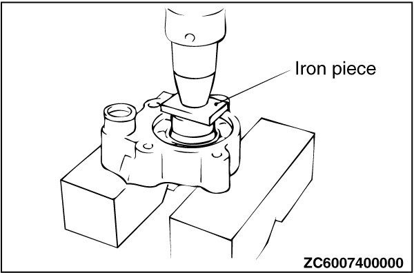
| 1.
Use a press and iron piece to remove the clutch gear and bearing together.
|
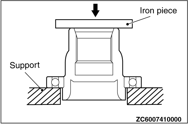
| 2.
Using a press, hold the supports against the bearing inner race, and separate the clutch
gear and bearing.
|
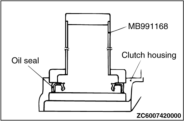
| Use special tool differential oil seal installer (MB991168) to tap the oil seal until
it is flush with the clutch housing.
|
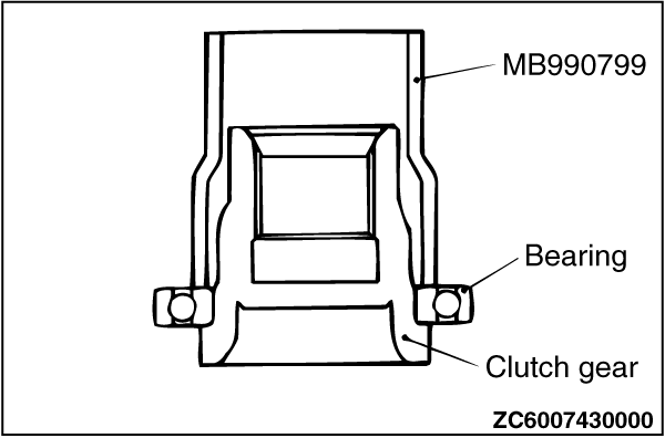
| 1.
Use special tool ball joint remover and installer A (MB990799) to press-fit the bearing
to the shoulder of the clutch gear.
|
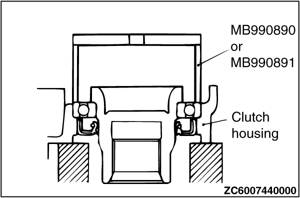
| 2.
| caution | Place special tool MB990890 or MB990891 against the outer race of the bearing.
|
Use special tool rear suspension housing base (MB990890 or MB990891) to press-fit the
bearing to the side of the clutch housing.
|
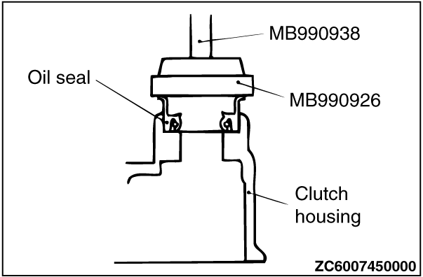
| Use the following special tools to press-fit the oil seal to the housing tube.
- Installer adapter (MB990926)
- Bar (MB990938)
|
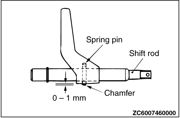
| Tap the spring pin from the chamfered side of the shaft rod until the projection length
becomes the length shown in the illustration.
|
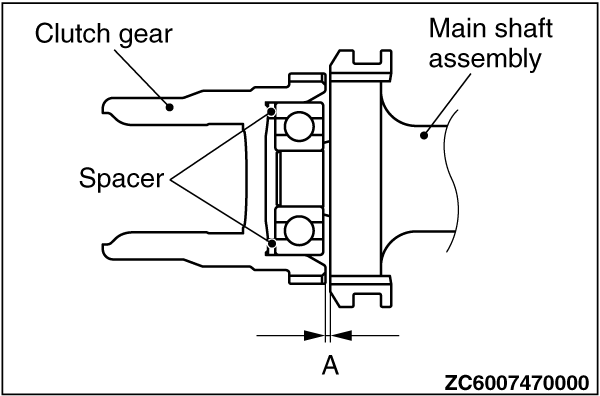
| 1.
Place the current spacer in the area shown in the illustration to check that the dimensions
shown in the illustration are within the standard values.
Standard Value (A): 0.05 - 0.3 mm
2.
If the dimensions are outside of the standard values, select the correct spacer type
to fit in the standard values.
Spacer type
| Part Number
| Thickness mm
| Part Number
| Thickness mm
| MR111526
| 1.1
| MR111530
| 2.1
| MR111527
| 1.35
| MR111531
| 2.35
| MR111528
| 1.6
| MR111532
| 2.6
| MR111529
| 1.85
| MR111533
| 2.85
|
|
|
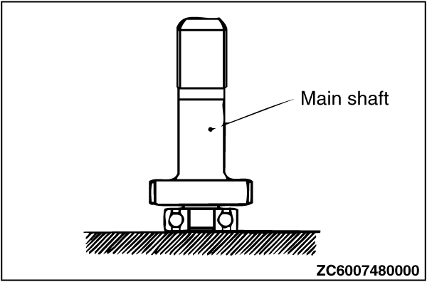
| Press-fit the bearing to the shoulder of the mainshaft.
|
)
)
)
)
)
)
)
)
)
)
)
